Example for Configuring an RR on an IPv6 VPN
If a large number of MP-IBGP peer relationships need to be set up between PEs on the backbone network, configuring an RR can reduce required MP-IBGP peer relationships and workload on PEs.
Networking Requirements
On the backbone network of an IPv6 VPN where a large number of VPNv6 peer relationships need to be set up, a P or PE can be configured as the RR. Then, other PEs only need to set up a VPNv6 peer relationship with the RR. This implementation reduces the number of VPNv6 peer relationships required between PEs as well as the workload on PEs.

To enhance the reliability of an RR-deployed network, two RRs can be configured for mutual backup.
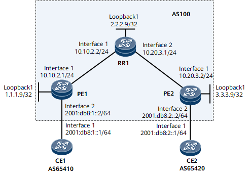
On the network shown in Figure 1, PE1, PE2, and RR1 reside in AS100, the backbone network; CE1 and CE2 belong to vpna. It is required that RR1 be configured as an RR for the IPv6 VPN.
Configuration Roadmap
The configuration roadmap is as follows:
Set up an MP-IBGP connection between each PE and the RR. There is no need to set up an MP-IBGP peer relationship between PEs.
Set up EBGP peer relationships between PEs and CEs.
Establish LDP LSPs between the PEs and RR on the backbone network.
Configure the RR to receive all VPNv6 routing information without filtering the information based on VPN targets.
Data Preparation
To complete the configuration, you need the following data:
MPLS LSR IDs of the PEs and RR1
Names of the VPN instances created on PE1 and PE2, RDs, and VPN targets of the VPN instance IPv6 address family
Routing protocol running between the PEs and CE for route exchange (EBGP in this configuration example)
Procedure
- Configure an IP address for each interface. For configuration details, see Configuration Files in this section.
- Configure an IGP on the MPLS backbone network so that devices on the backbone network can learn the route to one another's loopback interface.
This example uses OSPF as the IGP. For configuration details, see Configuration Files in this section.
After completing the configurations, run the display ip routing-table command on each device on the backbone network. The command output shows that the devices have learned the route to one another's loopback interface.
The following example uses the command output on PE1.
<PE1> display ip routing-table
Route Flags: R - relay, D - download to fib, T - to vpn-instance, B - black hole route
------------------------------------------------------------------------------
Routing Table: _public_
         Destinations : 11       Routes : 11
Destination/Mask    Proto  Pre  Cost       Flags  NextHop         Interface
        1.1.1.9/32  Direct 0    0              D  127.0.0.1       InLoopBack0
        2.2.2.9/32  OSPF   10   1              D  10.10.2.2       GigabitEthernet0/1/0
        3.3.3.9/32  OSPF   10   3              D  10.10.2.2       GigabitEthernet0/1/0
      10.10.2.0/24  Direct 0    0              D  10.10.2.1       GigabitEthernet0/1/0
      10.10.2.1/32  Direct 0    0              D  127.0.0.1       GigabitEthernet0/1/0
    10.10.2.255/32  Direct 0    0              D  127.0.0.1       GigabitEthernet0/1/0
      10.20.3.0/24  OSPF   10   2              D  10.10.2.2       GigabitEthernet0/1/0
      127.0.0.0/8   Direct 0    0              D  127.0.0.1       InLoopBack0
      127.0.0.1/32  Direct 0    0              D  127.0.0.1       InLoopBack0
127.255.255.255/32  Direct 0    0              D  127.0.0.1       InLoopBack0
255.255.255.255/32  Direct 0    0              D  127.0.0.1       InLoopBack0
- Configure MPLS and MPLS LDP both globally and per interface, and set up LDP LSPs between the PEs and RR1.
Configure MPLS and MPLS LDP globally and on public network interfaces of PE1, RR1, and PE2. For configuration details, see Configuration Files in this section.
After completing the configurations, run the display mpls ldp session command on each PE and RR1. The command output shows that the session state is Operational, which means that the LDP peer relationship is successfully set up.
The following example uses the command output on RR1.
<RR1> display mpls ldp session
2021-04-26 18:58:52.669

 LDP Session(s) in Public Network
 Codes: LAM(Label Advertisement Mode), SsnAge Unit(DDDD:HH:MM)
 An asterisk (*) before a session means the session is being deleted.
 --------------------------------------------------------------------------
 PeerID             Status      LAM  SsnRole  SsnAge       KASent/Rcv
 --------------------------------------------------------------------------
 1.1.1.9:0          Operational DU   Active   0000:00:02   11/11
 3.3.3.9:0          Operational DU   Passive  0000:00:01   8/8
 --------------------------------------------------------------------------
 TOTAL: 2 Session(s) Found.
- Configure an IPv6-address-family-supporting VPN instance on each PE.
For configuration details, see Example for Configuring Basic BGP/MPLS IPv6 VPN.
- Establish EBGP peer relationships between PEs and CEs to import VPN routes.
For configuration details, see Example for Configuring Basic BGP/MPLS IPv6 VPN.
After completing the configurations, run the display bgp vpnv6 vpn-instance peer command on PEs. The command output shows that the status of EBGP peer relationships between PEs and CEs is Established.
The following example uses the command output on PE1.
<PE1> display bgp vpnv6 vpn-instance vpna peer
 BGP local router ID : 1.1.1.9
 Local AS number : 100
 Total number of peers : 1                 Peers in established state : 1

  Peer            V          AS  MsgRcvd  MsgSent  OutQ  Up/Down       State PrefRcv

  2001:db8:1::1    4       65410     1385     1392     0 17:39:46 Established   1
- Establish a VPNv6 peer relationship between each PE and RR1.
# Configure PE1.
<PE1> system-view
[~PE1] bgp 100
[*PE1-bgp] peer 2.2.2.9 as-number 100
[*PE1-bgp] peer 2.2.2.9 connect-interface loopback 1
[*PE1-bgp] ipv6-family vpnv6
[*PE1-bgp-af-vpnv6] peer 2.2.2.9 enable
[*PE1-bgp-af-vpnv6] quit
[*PE1-bgp] quit
[*PE1] commit
# Configure RR1.
<RR1> system-view
[~RR1] bgp 100
[*RR1-bgp] peer 1.1.1.9 as-number 100
[*RR1-bgp] peer 1.1.1.9 connect-interface loopback 1
[*RR1-bgp] peer 3.3.3.9 as-number 100
[*RR1-bgp] peer 3.3.3.9 connect-interface loopback 1
[*RR1-bgp] ipv6-family vpnv6
[*RR1-bgp-af-vpnv6] peer 1.1.1.9 enable
[*RR1-bgp-af-vpnv6] peer 3.3.3.9 enable
[*RR1-bgp-af-vpnv6] quit
[*RR1-bgp] quit
[*RR1] commit
The configuration of PE2 is similar to the configuration of PE1. For configuration details, see Configuration Files in this section.
After completing the configurations, run the display bgp vpnv6 all peer command on PEs or RR1. The command output shows that the status of the EBGP peer relationships between the PEs and RR1 is Established.
The following example uses the command output on RR1.
[~RR1] display bgp vpnv6 all peer BGP local router ID : 2.2.2.9 Local AS number : 100 Total number of peers : 2 Peers in established state : 2 Peer V AS MsgRcvd MsgSent OutQ Up/Down State PrefRcv 1.1.1.9 4 100 1263 1530 0 19:46:01 Established 1 3.3.3.9 4 100 1170 1109 0 17:50:26 Established 1 - Configure VPNv6 route reflection on RR1.
# Configure RR1.
[~RR1] bgp 100
[*RR1-bgp] ipv6-family vpnv6
[*RR1-bgp-af-vpnv6] reflector cluster-id 100
[*RR1-bgp-af-vpnv6] peer 1.1.1.9 reflect-client
[*RR1-bgp-af-vpnv6] peer 3.3.3.9 reflect-client
[*RR1-bgp-af-vpnv6] peer 1.1.1.9 next-hop-local
[*RR1-bgp-af-vpnv6] peer 3.3.3.9 next-hop-local
[*RR1-bgp-af-vpnv6] undo policy vpn-target
[*RR1-bgp-af-vpnv6] quit
[*RR1-bgp] quit
[*RR1] commit
- Verify the configuration.
Run the display ipv6 routing-table vpn-instance command on PEs. The command output shows that the PEs have learned the routes to remote VPN sites and the recursive outbound interfaces point to RR1.
The following example uses the command output on PE1.
[~PE1] display ipv6 routing-table vpn-instance vpna
Routing Table : vpna
         Destinations : 4        Routes : 4

 Destination  : 2001:db8:1::                     PrefixLength : 64
 NextHop      : 2001:db8:1::2                    Preference   : 0
 Cost         : 0                               Protocol     : Direct
 RelayNextHop : ::                              TunnelID     : 0x0
 Interface    : GigabitEthernet0/1/8            Flags        : D

 Destination  : 2001:db8:1::2                    PrefixLength : 128
 NextHop      : ::1                             Preference   : 0
 Cost         : 0                               Protocol     : Direct
 RelayNextHop : ::                              TunnelID     : 0x0
 Interface    : GigabitEthernet0/1/8            Flags        : D

 Destination  : 2001:db8:2::                 PrefixLength : 64
 NextHop      : ::FFFF:2.2.2.9                 Preference   : 255
 Cost         : 0                              Protocol     : IBGP
 RelayNextHop : ::FFFF:10.10.2.2           TunnelID     : 0xa0010080
 Interface    : GigabitEthernet0/1/0         Flags        : RD

 Destination  : FE80::                          PrefixLength : 10
 NextHop      : ::                              Preference   : 0
 Cost         : 0                               Protocol     : Direct
 RelayNextHop : ::                              TunnelID     : 0x0
 Interface    : NULL0                           Flags        : D
CE1 and CE2 can successfully ping each other even if no VPNv6 peer relationship is configured between PE1 and PE2. This indicates that the RR is successfully configured.
Configuration Files
PE1 configuration file
#
 sysname PE1
#
ip vpn-instance vpna
 ipv6-family
  route-distinguisher 100:1
  apply-label per-instance
  vpn-target 1:1 export-extcommunity
  vpn-target 1:1 import-extcommunity
#
mpls lsr-id 1.1.1.9
#
mpls
#
mpls ldp
#
interface GigabitEthernet0/1/0
 undo shutdown
 ip address 10.10.2.1 255.255.255.0
 mpls
 mpls ldp
#
interface GigabitEthernet0/1/8
 undo shutdown
 ipv6 enable
 ip binding vpn-instance vpna
 ipv6 address 2001:db8:1::2/64
#
interface LoopBack1
 ip address 1.1.1.9 255.255.255.255
#
bgp 100
 peer 2.2.2.9 as-number 100
 peer 2.2.2.9 connect-interface LoopBack1
#
 ipv4-family unicast
  undo synchronization
  peer 2.2.2.9 enable
#
 ipv6-family vpnv6
  policy vpn-target
  peer 2.2.2.9 enable
 #
 ipv6-family vpn-instance vpna
  peer 2001:db8:1::1 as-number 65410
  import-route direct
#
ospf 1
 area 0.0.0.0
  network 1.1.1.9 0.0.0.0
  network 10.10.2.0 0.0.0.255
#
return
RR1 configuration file
#
 sysname RR1
#
mpls lsr-id 2.2.2.9
#
mpls
#
mpls ldp
#
interface GigabitEthernet0/1/0
 undo shutdown
 ip address 10.10.2.2 255.255.255.0
 mpls
 mpls ldp
#
interface GigabitEthernet0/1/8
 undo shutdown
 ip address 10.20.3.1 255.255.255.0
 mpls
 mpls ldp
#
interface LoopBack1
 ip address 2.2.2.9 255.255.255.255
#
bgp 100
 peer 1.1.1.9 as-number 100
 peer 1.1.1.9 connect-interface LoopBack1
 peer 3.3.3.9 as-number 100
 peer 3.3.3.9 connect-interface LoopBack1
#
 ipv4-family unicast
  undo synchronization
  peer 1.1.1.9 enable
  peer 3.3.3.9 enable
 #
 ipv6-family vpnv6
  reflector cluster-id 100
  undo policy vpn-target
  peer 1.1.1.9 enable
  peer 1.1.1.9 reflect-client
  peer 1.1.1.9 next-hop-local
  peer 3.3.3.9 enable
  peer 3.3.3.9 reflect-client
  peer 3.3.3.9 next-hop-local
#
ospf 1
 area 0.0.0.0
  network 10.10.2.0 0.0.0.255
  network 10.20.3.0 0.0.0.255
  network 2.2.2.9 0.0.0.0
#
return
PE2 configuration file
#
sysname PE2
#
ip vpn-instance vpna
 ipv6-family
  route-distinguisher 100:1
  apply-label per-instance
  vpn-target 1:1 export-extcommunity
  vpn-target 1:1 import-extcommunity
#
mpls lsr-id 3.3.3.9
#
mpls
#
mpls ldp
#
interface GigabitEthernet0/1/0
 undo shutdown
 ip address 10.20.3.2 255.255.255.0
 mpls
 mpls ldp
#
interface GigabitEthernet0/1/8
 undo shutdown
 ipv6 enable
 ip binding vpn-instance vpna
 ipv6 address 2001:db8:2::2/64
#
interface LoopBack1
 ip address 3.3.3.9 255.255.255.255
#
bgp 100
 peer 2.2.2.9 as-number 100
 peer 2.2.2.9 connect-interface LoopBack1
 #
 ipv4-family unicast
  undo synchronization
  peer 2.2.2.9 enable
 #
 ipv6-family vpnv6
  policy vpn-target
  peer 2.2.2.9 enable
 #
 ipv6-family vpn-instance vpna
  peer 2001:db8:2::1 as-number 65420
  import-route direct
#
ospf 1
 area 0.0.0.0
  network 3.3.3.9 0.0.0.0
  network 10.20.3.0 0.0.0.255
#
return
CE1 configuration file
#
 sysname CE1
#
interface GigabitEthernet0/1/0
 undo shutdown
 ipv6 enable
 ipv6 address 2001:db8:1::1/64
#
bgp 65410
 router-id 10.10.10.10
 peer 2001:db8:1::2 as-number 100
 #
 ipv6-family unicast
  undo synchronization
  peer 2001:db8:1::2 enable
  import-route direct
#
return
CE2 configuration file
#
 sysname CE2
#
interface GigabitEthernet0/1/0
 undo shutdown
 ipv6 enable
 ipv6 address 2001:db8:2::1/64
#
bgp 65420
 router-id 30.30.30.30
 peer 2001:db8:2::2 as-number 100
 #
 ipv6-family unicast
  undo synchronization
  peer 2001:db8:2::2 enable
  import-route direct
#
return