Example for Configuring Multicast VPN in MDT-SAFI A-D Mode
The MDT-SAFI A-D mode can be adopted to deploy the multicast VPN in network. In this manner, the multicast VPN PE information can be automatically discovered, the PIM-SSM MDT can be established on the public network, and multicast VPN services can be transmitted.
Networking Requirements
After the BGP A-D mode is adopted, information about the multicast VPN PEs can be discovered in the following way: A new address family is defined in the Subsequent Address Family Identifier (SAFI) message advertised by BGP. In this manner, after the multicast VPN is configured on a PE, the multicast VPN configurations, including the RD and the Share-Group address, can be advertised to all BGP peers. After a remote PE (a BGP peer) receives the SAFI message advertised through BGP, the remote PE compares the Share-Group address carried in the message with its Share-Group address. If the Share-Group addresses are the same, it indicates the remote PE is in the same VPN with the local PE. The remote PE then uses the SAFI message to establish the Protocol Independent Multicast-Source-Specific Multicast (PIM-SSM) multicast distribution tree (MDT) for transmitting multicast VPN services.
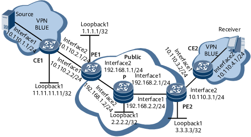
As shown in Figure 1, in the single-AS MPLS/BGP VPN, PE1 and PE2 are added to the VPN instance BLUE, the IP address of the Share-Group is within the SSM group address range. The MDT-SAFI address family is enabled in the BGP view of each PE, and the MDT-SAFI A-D mode is enabled for the VPN instance BLUE. The site to which CE1 belongs is connected to the multicast source Source of the VPN instance BLUE, and CE2 is connected to VPN users.
Based on the BGP A-D mechanism, every PE obtains and records information about all its PEs in the VPN instance BLUE, and directly establishes the PIM-SSM MDT on the public network for transmitting multicast VPN services. In this manner, the multicast data is sent from the Source to the receiver.

Configuration Roadmap
The configuration roadmap is as follows:
Configure a VPN instance named BLUE enabled with the IPv4 address family on each PE, and configure the Share-Group address, and the MTunnel to be bound for the VPN instance. Then, bind the interface that connects each PE to the corresponding CE to the VPN instance BLUE.
Configure a unicast routing protocol and enable the multicast function on the public network and the VPN instance, ensuring that multicast routes are reachable on the public network and in the VPN instance.
Configure basic MPLS functions and MPLS LDP, and set up LDP label switched paths (LSPs) on the public network.
Configure the Multiprotocol Internal Border Gateway Protocol (MP-IBGP) peer relationship between PEs, and configure a unicast routing protocol between each PE and the corresponding CE, ensuring that routes are reachable between PEs and the corresponding CEs.
Configure the MDT-SAFI A-D mode in the VPN instance IPv4 address family view of each PE, and enable route exchange with the specific peer (peer group) in the address family view. In this manner, the receiver can receive the multicast data from the multicast source.
Globally configure the MDT-SAFI address family in the BGP view of each PE.
Procedure
- Configure a VPN instance named BLUE enabled with the IPv4 address family on each PE, and configure the Share-Group address, and the MTunnel to be bound for the VPN instance. Then, bind the interface that connects each PE to the corresponding CE to the VPN instance.
# Create a VPN instance named BLUE enabled with the IPv4 address on PE1 and globally enable the multicast function in the VPN instance; configure the Share-Group address for the VPN instance; bind the Share-Group address to MTunnel 0; bind GE 0/1/0 that connects PE1 to CE1 to the VPN instance.
<HUAWEI> system-view
[~HUAWEI] sysname PE1
[*HUAWEI] commit
[~PE1] ip vpn-instance BLUE
[*PE1-vpn-instance-BLUE] ipv4-family
[*PE1-vpn-instance-BLUE-af-ipv4] route-distinguisher 100:1
[*PE1-vpn-instance-BLUE-af-ipv4] vpn-target 100:1 both
[*PE1-vpn-instance-BLUE-af-ipv4] multicast routing-enable
[*PE1-vpn-instance-BLUE-af-ipv4] multicast-domain share-group 232.2.2.0 binding mtunnel 0
[*PE1-vpn-instance-BLUE-af-ipv4] quit
[*PE1-vpn-instance-BLUE] quit
[*PE1] commit
[~PE1] interface gigabitethernet 0/1/0
[*PE1-GigabitEthernet0/1/0] ip binding vpn-instance BLUE
[*PE1-GigabitEthernet0/1/0] quit
[*PE1] commit
# Create a VPN instance named BLUE enabled with the IPv4 address on PE2 and globally enable the multicast function in the VPN instance; configure the Share-Group address for the VPN instance; bind the Share-Group address to MTunnel 0; bind GE 0/1/8 that connects PE2 to CE2 to the VPN instance.
<HUAWEI> system-view
[~HUAWEI] sysname PE2
[*HUAWEI] commit
[~PE2] ip vpn-instance BLUE
[*PE2-vpn-instance-BLUE] ipv4-family
[*PE2-vpn-instance-BLUE-af-ipv4] route-distinguisher 200:1
[*PE2-vpn-instance-BLUE-af-ipv4] vpn-target 200:1 both
[*PE2-vpn-instance-BLUE-af-ipv4] multicast routing-enable
[*PE2-vpn-instance-BLUE-af-ipv4] multicast-domain share-group 232.2.2.0 binding mtunnel 0
[*PE2-vpn-instance-BLUE-af-ipv4] quit
[*PE2-vpn-instance-BLUE] quit
[*PE2] commit
[~PE2] interface gigabitethernet 0/1/8
[*PE2-GigabitEthernet0/1/8] ip binding vpn-instance BLUE
[*PE2-GigabitEthernet0/1/8] quit
[*PE2] commit
- Configure a unicast routing protocol and enable the multicast function on the public network, ensuring that multicast routes are reachable on the public network.
# Configure OSPF on the public network, ensuring that unicast routes are reachable. Then, globally enable the multicast function and enable PIM-SM on interfaces, ensuring that the multicast network runs normally.
# Configure PE1.
[~PE1] multicast routing-enable
[*PE1] commit
[~PE1] interface loopback 1
[~PE1-LoopBack1] ip address 1.1.1.1 32
[*PE1-LoopBack1] pim sm
[*PE1-LoopBack1] quit
[*PE1] commit
[~PE1] interface gigabitethernet 0/1/8
[~PE1-GigabitEthernet0/1/8] ip address 192.168.1.1 24
[*PE1-GigabitEthernet0/1/8] pim sm
[*PE1-GigabitEthernet0/1/8] quit
[*PE1] commit
[~PE1] ospf
[*PE1-ospf-1] area 0
[*PE1-ospf-1-area-0.0.0.0] network 1.1.1.1 0.0.0.0
[*PE1-ospf-1-area-0.0.0.0] network 192.168.1.0 0.0.0.255
[*PE1-ospf-1-area-0.0.0.0] quit
[*PE1-ospf-1] quit
[*PE1] commit
# Configure the P.
<HUAWEI> system-view
[~HUAWEI] sysname P
[*HUAWEI] commit
[~P] multicast routing-enable
[*P] commit
[~P] interface loopback 1
[~P-LoopBack1] ip address 2.2.2.2 32
[*P-LoopBack1] pim sm
[*P-LoopBack1] quit
[*P] commit
[~P] interface gigabitethernet 0/1/8
[~P-GigabitEthernet0/1/8] ip address 192.168.1.2 24
[*P-GigabitEthernet0/1/8] pim sm
[*P-GigabitEthernet0/1/8] quit
[*P] commit
[~P] interface gigabitethernet 0/1/0
[~P-GigabitEthernet0/1/0] ip address 192.168.2.1 24
[*P-GigabitEthernet0/1/0] pim sm
[*P-GigabitEthernet0/1/0] quit
[*P] commit
[~P] ospf
[*P-ospf-1] area 0
[*P-ospf-1-area-0.0.0.0] network 2.2.2.2 0.0.0.0
[*P-ospf-1-area-0.0.0.0] network 192.168.1.0 0.0.0.255
[*P-ospf-1-area-0.0.0.0] network 192.168.2.0 0.0.0.255
[*P-ospf-1-area-0.0.0.0] quit
[*P-ospf-1] quit
[*P] commit
# Configure PE2.
[~PE2] multicast routing-enable
[*PE2] commit
[~PE2] interface loopback 1
[~PE2-LoopBack1] ip address 3.3.3.3 32
[*PE2-LoopBack1] pim sm
[*PE2-LoopBack1] quit
[*PE2] commit
[~PE2] interface gigabitethernet 0/1/0
[~PE2-Gigabitethernet0/1/0] ip address 192.168.2.2 24
[*PE2-Gigabitethernet0/1/0] pim sm
[*PE2-Gigabitethernet0/1/0] quit
[*PE2] commit
[~PE2] ospf
[*PE2-ospf-1] area 0
[*PE2-ospf-1-area-0.0.0.0] network 3.3.3.3 0.0.0.0
[*PE2-ospf-1-area-0.0.0.0] network 192.168.2.0 0.0.0.255
[*PE2-ospf-1-area-0.0.0.0] quit
[*PE2-ospf-1] quit
[*PE2] commit
- Configure a unicast routing protocol and enable the multicast function for the VPN instance BLUE, ensuring that multicast routes of the VPN instance are reachable.
# Configure OSPF for the VPN instance BLUE, ensuring that unicast routes are reachable. Then, globally enable the multicast function and enable PIM-SM on interfaces, ensuring that the multicast network runs normally.
# Configure CE1.
<HUAWEI> system-view
[~HUAWEI] sysname CE1
[*HUAWEI] commit
[~CE1] multicast routing-enable
[*CE1] commit
[~CE1] interface loopback 1
[~CE1-LoopBack1] ip address 11.11.11.11 32
[*CE1-LoopBack1] pim sm
[*CE1-LoopBack1] quit
[*CE1] commit
[~CE1] interface gigabitethernet 0/1/0
[~CE1-GigabitEthernet0/1/0] ip address 10.110.1.1 24
[*CE1-GigabitEthernet0/1/0] pim sm
[*CE1-GigabitEthernet0/1/0] quit
[*CE1] commit
[~CE1] interface gigabitethernet 0/1/8
[~CE1-GigabitEthernet0/1/8] ip address 10.110.2.1 24
[*CE1-GigabitEthernet0/1/8] pim sm
[*CE1-GigabitEthernet0/1/8] quit
[*CE1] commit
[~CE1] ospf 2
[*CE1-ospf-2] area 0
[*CE1-ospf-2-area-0.0.0.0] network 11.11.11.11 0.0.0.0
[*CE1-ospf-2-area-0.0.0.0] network 10.110.1.0 0.0.0.255
[*CE1-ospf-2-area-0.0.0.0] network 10.110.2.0 0.0.0.255
[*CE1-ospf-2-area-0.0.0.0] quit
[*CE1-ospf-2] quit
[*CE1] commit
# Configure PE1.
[~PE1] interface gigabitethernet 0/1/0
[~PE1-GigabitEthernet0/1/0] ip address 10.110.2.2 24
[*PE1-GigabitEthernet0/1/0] pim sm
[*PE1-GigabitEthernet0/1/0] quit
[*PE1] commit
[~PE1] ospf 2 vpn-instance BLUE
[*PE1-ospf-2] area 0
[*PE1-ospf-2-area-0.0.0.0] network 10.110.2.0 0.0.0.255
[*PE1-ospf-2-area-0.0.0.0] quit
[*PE1-ospf-2] quit
[*PE1] commit
# Configure PE2.
[~PE2] interface gigabitethernet 0/1/8
[~PE2-GigabitEthernet0/1/8] ip address 10.110.3.1 24
[*PE2-GigabitEthernet0/1/8] pim sm
[*PE2-GigabitEthernet0/1/8] quit
[*PE2] commit
[~PE2] ospf 2 vpn-instance BLUE
[*PE2-ospf-2] area 0
[*PE2-ospf-2-area-0.0.0.0] network 10.110.3.0 0.0.0.255
[*PE2-ospf-2-area-0.0.0.0] quit
[*PE2-ospf-2] quit
[*PE2] commit
# Configure CE2.
<HUAWEI> system-view
[~HUAWEI] sysname CE2
[*HUAWEI] commit
[~CE2] multicast routing-enable
[*CE2] commit
[~CE2] interface gigabitethernet 0/1/0
[~CE2-GigabitEthernet0/1/0] ip address 10.110.3.2 24
[*CE2-GigabitEthernet0/1/0] pim sm
[*CE2-GigabitEthernet0/1/0] quit
[*CE2] commit
[~CE2] interface gigabitethernet 0/1/8
[~CE2-GigabitEthernet0/1/8] ip address 10.110.4.1 24
[*CE2-GigabitEthernet0/1/8] pim sm
[*CE2-GigabitEthernet0/1/8] quit
[*CE2] commit
[~CE2] ospf 2
[*CE2-ospf-2] area 0
[*CE2-ospf-2-area-0.0.0.0] network 10.110.3.0 0.0.0.255
[*CE2-ospf-2-area-0.0.0.0] network 10.110.4.0 0.0.0.255
[*CE2-ospf-2-area-0.0.0.0] quit
[*CE2-ospf-2] quit
[*CE2] commit
- Configure basic MPLS functions and MPLS LDP and set up LDP LSPs on the public network.
Configure the router IDs and MPLS label switching router (LSR) IDs of the PEs and the P device, and enable MPLS and MPLS LDP globally and in the interface view.
# Configure PE1.
[~PE1] router id 1.1.1.1
[*PE1] mpls lsr-id 1.1.1.1
[*PE1] mpls
[*PE1-mpls] quit
[*PE1] mpls ldp
[*PE1-mpls-ldp] quit
[*PE1] commit
[~PE1] interface gigabitethernet 0/1/8
[~PE1-GigabitEthernet0/1/8] mpls
[*PE1-GigabitEthernet0/1/8] mpls ldp
[*PE1-GigabitEthernet0/1/8] quit
[*PE1] commit
# Configure the P.
[~P] router id 2.2.2.2
[*P] mpls lsr-id 2.2.2.2
[*P] mpls
[*P-mpls] quit
[*P] mpls ldp
[*P-mpls-ldp] quit
[*P] commit
[~P] interface gigabitethernet 0/1/8
[~P-GigabitEthernet0/1/8] mpls
[*P-GigabitEthernet0/1/8] mpls ldp
[*P-GigabitEthernet0/1/8] quit
[*P] commit
[~P] interface gigabitethernet 0/1/0
[~P-GigabitEthernet0/1/0] mpls
[*P-GigabitEthernet0/1/0] mpls ldp
[*P-GigabitEthernet0/1/0] quit
[*P] commit
# Configure PE2.
[~PE2] router id 3.3.3.3
[*PE2] mpls lsr-id 3.3.3.3
[*PE2] mpls
[*PE2-mpls] quit
[*PE2] mpls ldp
[*PE2-mpls-ldp] quit
[*PE2] commit
[~PE2] interface gigabitethernet 0/1/0
[~PE2-GigabitEthernet0/1/0] mpls
[*PE2-GigabitEthernet0/1/0] mpls ldp
[*PE2-GigabitEthernet0/1/0] quit
[*PE2] commit
- Establish an MP-IBGP peer relationship between PEs; configure a unicast routing protocol between a PE and a CE to ensure that the PE and the CE are routable.
# Configure PE1 and PE2 as MP-IBGP peers of each other and configure route exchange between OSPF multi-instance and BGP, ensuring that routes are reachable between PEs and CEs.
# Configure PE1.
[~PE1] bgp 100
[*PE1-bgp] peer 3.3.3.3 as-number 100
[*PE1-bgp] peer 3.3.3.3 connect-interface LoopBack 1
[*PE1-bgp] ipv4-family vpnv4
[*PE1-bgp-af-vpnv4] peer 3.3.3.3 enable
[*PE1-bgp-af-vpnv4] quit
[*PE1-bgp] commit
[~PE1-bgp] ipv4-family vpn-instance BLUE
[*PE1-bgp-BLUE] import-route ospf 2
[*PE1-bgp-BLUE] import-route direct
[*PE1-bgp-BLUE] quit
[*PE1-bgp] quit
[*PE1] commit
[~PE1] ospf 2 vpn-instance BLUE
[*PE1-ospf-2] import-route bgp
[*PE1-ospf-2] quit
[*PE1] commit
# Configure PE2.
[~PE2] bgp 100
[*PE2-bgp] peer 1.1.1.1 as-number 100
[*PE2-bgp] peer 1.1.1.1 connect-interface LoopBack 1
[*PE2-bgp] ipv4-family vpnv4
[*PE2-bgp-af-vpnv4] peer 1.1.1.1 enable
[*PE2-bgp-af-vpnv4] quit
[*PE2-bgp] commit
[~PE2-bgp] ipv4-family vpn-instance BLUE
[*PE2-bgp-BLUE] import-route ospf 2
[*PE2-bgp-BLUE] import-route direct
[*PE2-bgp-BLUE] quit
[*PE2-bgp] quit
[*PE2] commit
[~PE2] ospf 2 vpn-instance BLUE
[*PE2-ospf-2] import-route bgp
[*PE2-ospf-2] quit
[*PE2] commit
- Assign an IP address to the MTunnel interface (MTI).
# On each PE, configure the IP address of loopback 1 as the IP address of the MTI (in this manner, the system automatically binds the MTI to the VPN instance BLUE).
# Configure PE1.
[~PE1] interface MTunnel 0
[~PE1-MTunnel0] ip address 1.1.1.1 32
[*PE1-MTunnel0] quit
[*PE1] commit
# Configure PE2.
[~PE2] interface MTunnel 0
[~PE2-MTunnel0] ip address 3.3.3.3 32
[*PE2-MTunnel0] quit
[*PE2] commit
- Configure the RP of the VPN instance BLUE.
# Configure loopback 1 of CE1 as the Candidate-BSR (C-BSR) and Candidate-RP (C-RP) that serve the VPN instance BLUE.
[~CE1] pim
[*CE1-pim] c-bsr loopback 1
[*CE1-pim] c-rp loopback 1
[*CE1-pim] quit
[*CE1] commit
- Configure the MDT-SAFI A-D mode for the VPN instance BLUE.
# Configure the MDT-SAFI address family in the BGP view and configure route exchange with the specific peer. Then, configure the MDT-SAFI A-D mode in the IPv4 address family view of the VPN instance BLUE to implement the BGP A-D function.
# Configure PE1.
[~PE1] bgp 100
[*PE1-bgp] ipv4-family mdt
[*PE1-bgp-af-mdt] peer 3.3.3.3 enable
[*PE1-bgp-af-mdt] quit
[*PE1-bgp] quit
[*PE1] commit
[~PE1] ip vpn-instance BLUE
[*PE1-vpn-instance-BLUE] ipv4-family
[*PE1-vpn-instance-BLUE-af-ipv4] auto-discovery mdt
[*PE1-vpn-instance-BLUE-af-ipv4] quit
[*PE1-vpn-instance-BLUE] quit
[*PE1] commit
# Configure PE2.
[~PE2] bgp 100
[*PE2-bgp] ipv4-family mdt
[*PE2-bgp-af-mdt] peer 1.1.1.1 enable
[*PE2-bgp-af-mdt] quit
[*PE2-bgp] quit
[*PE2] commit
[~PE2] ip vpn-instance BLUE
[*PE2-vpn-instance-BLUE] ipv4-family
[*PE2-vpn-instance-BLUE-af-ipv4] auto-discovery mdt
[*PE2-vpn-instance-BLUE-af-ipv4] quit
[*PE2-vpn-instance-BLUE] quit
[*PE2] commit
- Verify the configuration.
By checking the configuration result, you can view that Receiver can receive multicast data from Source.
Run the display pim routing-table command on PE2 to view the PIM routing table of the public network. You can find that the PIM-SSM MDT is directly established on the public network.
<PE2> display pim routing-table
 VPN-Instance: public net
 Total 2 (S, G) entries

 (1.1.1.1, 232.2.2.0)
     Protocol: pim-ssm, Flag: SG_RCVR
     UpTime: 00:05:30
     Upstream interface: GigabitEthernet0/1/0
         Upstream neighbor: 192.168.2.1
         RPF prime neighbor: 192.168.2.1
     Downstream interface(s) information:
     Total number of downstreams: 1
        1: VPN-Instance: BLUE
             Protocol: MD, UpTime: 00:05:30, Expires: -

 (3.3.3.3, 232.2.2.0)
     Protocol: pim-ssm, Flag: LOC
     UpTime: 00:05:30
     Upstream interface: LoopBack1
         Upstream neighbor: NULL
         RPF prime neighbor: NULL
     Downstream interface(s) information:
     Total number of downstreams: 1
        1: GigabitEthernet0/1/0
             Protocol: pim-ssm, UpTime: 00:05:30, Expires: 00:03:01
Run the display pim vpn-instance BLUE routing-table on PE2 to view the PIM routing table of the VPN instance BLUE. You can find that PIM entries of the VPN instance BLUE are created on PE2.
<PE2> display pim vpn-instance BLUE routing-table
 VPN-Instance: BLUE
 Total 1 (*, G) entry; 1 (S, G) entry

 (*, 225.0.0.1)
     RP: 11.11.11.11
     Protocol: pim-sm, Flag: WC
     UpTime: 00:05:51
     Upstream interface: MTunnel0
         Upstream neighbor: 1.1.1.1
         RPF prime neighbor: 1.1.1.1
     Downstream interface(s) information:
     Total number of downstreams: 1
        1: GigabitEthernet0/1/8
             Protocol: pim-sm, UpTime: 00:05:51, Expires: 00:02:40

 (10.110.1.100, 225.0.0.1)
     RP: 11.11.11.11
     Protocol: pim-sm, Flag: SPT ACT
     UpTime: 00:05:50
     Upstream interface: MTunnel0
         Upstream neighbor: 1.1.1.1
         RPF prime neighbor: 1.1.1.1
     Downstream interface(s) information:
     Total number of downstreams: 1
        1: GigabitEthernet0/1/8
             Protocol: pim-sm, UpTime: 00:05:50, Expires: 00:02:41
Run the display multicast vpn-instance BLUE routing-table command on PE2 to view the multicast routing table of the VPN instance BLUE. The following command output shows that multicast data has reached the receiver PE2.
<PE2> display multicast vpn-instance BLUE routing-table
Multicast routing table of VPN-Instance: BLUE
 Total 1 entry

 00001. (10.110.1.100, 225.0.0.1)
       Uptime: 00:06:25
       Upstream Interface: MTunnel0
       List of 1 downstream interface
           1: GigabitEthernet0/1/8
Run the display multicast-domain vpn-instance BLUE share-group command on PE2 to view information about the Share-Group in the VPN instance BLUE. You can find the Share-Group address of the remote PE is 232.2.2.0, and IP address of the remote PE is 1.1.1.1.
<PE2> display multicast-domain vpn-instance BLUE share-group
MD local share-group information for VPN-Instance: BLUE
  Share-group: 232.2.2.0
  MTunnel address: 3.3.3.3
MD remote share-group information for VPN-Instance: BLUE
  Share-group     Peer-address
  232.2.2.0       1.1.1.1
After the preceding configurations, run the display pim routing-table command on CE2 to view the PIM routing table. You can find that the receiver can receive multicast data from the multicast source.
<CE2> display pim routing-table
 VPN-Instance: public net
 Total 1 (*, G) entry; 1 (S, G) entry

 (*, 225.0.0.1)
     RP: 11.11.11.11
     Protocol: pim-sm, Flag: WC
     UpTime: 00:21:58
     Upstream interface: GigabitEthernet0/1/0
         Upstream neighbor: 10.110.3.1
         RPF prime neighbor: 10.110.3.1
     Downstream interface(s) information:
     Total number of downstreams: 1
        1: GigabitEthernet0/1/8
             Protocol: static, UpTime: 00:21:58, Expires: -

 (10.110.1.100, 225.0.0.1)
     RP: 11.11.11.11
     Protocol: pim-sm, Flag: SPT ACT
     UpTime: 00:07:27
     Upstream interface: GigabitEthernet0/1/0
         Upstream neighbor: 10.110.3.1
         RPF prime neighbor: 10.110.3.1
     Downstream interface(s) information:
     Total number of downstreams: 1
        1: GigabitEthernet0/1/8
             Protocol: pim-sm, UpTime: 00:07:27, Expires: -
Configuration Files
PE1 configuration file
#
sysname PE1
#
router id 1.1.1.1
#
multicast routing-enable
#
ip vpn-instance BLUE
 ipv4-family
  route-distinguisher 100:1
  apply-label per-instance
  vpn-target 100:1 export-extcommunity
  vpn-target 100:1 import-extcommunity
  multicast routing-enable
  multicast-domain share-group 232.2.2.0 binding mtunnel 0
  auto-discovery mdt
#
mpls lsr-id 1.1.1.1
#
mpls
#
mpls ldp
#
interface GigabitEthernet0/1/0
 undo shutdown
 ip binding vpn-instance BLUE
 ip address 10.110.2.2 255.255.255.0
 pim sm
#
interface GigabitEthernet0/1/8
 undo shutdown
 ip address 192.168.1.1 255.255.255.0
 pim sm
 mpls
 mpls ldp
#
interface LoopBack1
 ip address 1.1.1.1 255.255.255.255
 pim sm
#
interface MTunnel0
 ip binding vpn-instance BLUE
 ip address 1.1.1.1 255.255.255.255
#
bgp 100
 peer 3.3.3.3 as-number 100
 peer 3.3.3.3 connect-interface LoopBack1
 #
 ipv4-family unicast
  undo synchronization
  peer 3.3.3.3 enable
 #
 ipv4-family vpnv4
  policy vpn-target
  peer 3.3.3.3 enable
 #
 ipv4-family vpn-instance BLUE
  import-route direct
  import-route ospf 2
 #
 ipv4-family mdt
  policy vpn-target
  peer 3.3.3.3 enable
#
ospf 1
 area 0.0.0.0
  network 1.1.1.1 0.0.0.0
  network 192.168.1.0 0.0.0.255
#
ospf 2 vpn-instance BLUE
 import-route bgp
 area 0.0.0.0
  network 10.110.2.0 0.0.0.255
#
return
P configuration file
#
sysname P
#
router id 2.2.2.2
#
multicast routing-enable
#
mpls lsr-id 2.2.2.2
#
mpls
#
mpls ldp
#
interface GigabitEthernet0/1/0
 undo shutdown
 ip address 192.168.2.1 255.255.255.0
 pim sm
 mpls
 mpls ldp
#
interface GigabitEthernet0/1/8
 undo shutdown
 ip address 192.168.1.2 255.255.255.0
 pim sm
 mpls
 mpls ldp
#
interface LoopBack1
 ip address 2.2.2.2 255.255.255.255
 pim sm
#
ospf 1
 area 0.0.0.0
  network 2.2.2.2 0.0.0.0
  network 192.168.1.0 0.0.0.255
  network 192.168.2.0 0.0.0.255
#
return
PE2 configuration file
#
sysname PE2
#
router id 3.3.3.3
#
multicast routing-enable
#
ip vpn-instance BLUE
 ipv4-family
  route-distinguisher 200:1
 apply-label per-instance
  vpn-target 200:1 export-extcommunity
  vpn-target 200:1 import-extcommunity
  multicast routing-enable
  multicast-domain share-group 232.2.2.0 binding mtunnel 0
  auto-discovery mdt
#
mpls lsr-id 3.3.3.3
#
mpls
#
mpls ldp
#
interface GigabitEthernet0/1/0
 undo shutdown
 ip address 192.168.2.2 255.255.255.0
 pim sm
 mpls
 mpls ldp
#
interface GigabitEthernet0/1/8
 undo shutdown
 ip binding vpn-instance BLUE
 ip address 10.110.3.1 255.255.255.0
 pim sm
#
interface LoopBack1
 ip address 3.3.3.3 255.255.255.255
 pim sm
#
interface MTunnel0
 ip binding vpn-instance BLUE
 ip address 3.3.3.3 255.255.255.255
#
bgp 100
 peer 1.1.1.1 as-number 100
 peer 1.1.1.1 connect-interface LoopBack1
 #
 ipv4-family unicast
  undo synchronization
  peer 1.1.1.1 enable
 #
 ipv4-family vpnv4
  policy vpn-target
  peer 1.1.1.1 enable
 #
 ipv4-family vpn-instance BLUE
  import-route direct
  import-route ospf 2
 #
 ipv4-family mdt
  policy vpn-target
  peer 1.1.1.1 enable
#
ospf 1
 area 0.0.0.0
  network 3.3.3.3 0.0.0.0
  network 192.168.2.0 0.0.0.255
#
ospf 2 vpn-instance BLUE
 import-route bgp
 area 0.0.0.0
  network 10.110.3.0 0.0.0.255
#
return
CE1 configuration file
#
sysname CE1
#
multicast routing-enable
#
interface GigabitEthernet0/1/0
 undo shutdown
 ip address 10.110.1.1 255.255.255.0
 pim sm
#
interface GigabitEthernet0/1/8
 undo shutdown
 ip address 10.110.2.1 255.255.255.0
 pim sm
#
interface LoopBack1
 ip address 11.11.11.11 255.255.255.255
 pim sm
#
ospf 2
 area 0.0.0.0
  network 10.110.1.0 0.0.0.255
  network 10.110.2.0 0.0.0.255
  network 11.11.11.11 0.0.0.0
#
pim
 c-bsr LoopBack1
 c-rp LoopBack1
#
return
CE2 configuration file
#
sysname CE2
#
multicast routing-enable
#
interface GigabitEthernet0/1/0
 undo shutdown
 ip address 10.110.3.2 255.255.255.0
 pim sm
#
interface GigabitEthernet0/1/8
 undo shutdown
 ip address 10.110.4.1 255.255.255.0
 pim sm
 igmp enable
 igmp static-group 225.0.0.1
#
ospf 2
 area 0.0.0.0
  network 10.110.3.0 0.0.0.255
  network 10.110.4.0 0.0.0.255
#
return