Example for Configuring Any Proxy ND
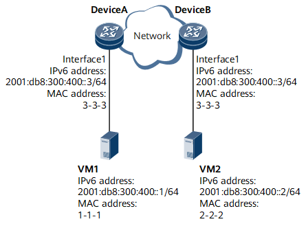
This section provides an example for configuring any proxy ND in a scenario where two hosts are on the same network segment but different physical networks and the gateways connecting to the two hosts have the same IP address.
Networking Requirements
In scenarios where servers are partitioned into VMs, to allow flexible deployment and migration of VMs on multiple servers or gateways, the common solution is to configure Layer 2 interworking between multiple gateways. However, this approach may lead to larger Layer 2 domains on the network and risks of broadcast storms. To resolve this problem, a common way is to enable any proxy ND on a VM gateway so that the gateway sends its own MAC address to the source VM and the traffic sent from the source VM to other VMs is transmitted over routes.
Configuration Roadmap
The configuration roadmap is as follows:
Configure a VLAN so that the VMs which need to communicate with each other reside in the same VLAN.
Configure interface attributes and bind the interfaces to the VLAN.
Assign IPv6 addresses to interfaces.
Enable any proxy ND on the VLANIF interfaces to which VMs are connected. After receiving an NS packet (for a destination VM's MAC address) from a source VM, the gateway enabled with any proxy ND responds with its own MAC address for subsequent data forwarding.
Configure advertisement of IPv6 NDP Vlink direct routes.
Data Preparation
To complete the configuration, you need the following data:
ID of the VLAN to which devices and VMs belong
IPv6 addresses of VM-side interfaces
IPv6 addresses of VMs
Procedure
- Create a VLAN.

Configure the same VLAN ID on Device A and Device B.
# Configure Device A.<HUAWEI> system-view [~HUAWEI] sysname DeviceA [*HUAWEI] commit [~DeviceA] vlan 10 [*DeviceA-vlan10] commit [~DeviceA-vlan10] quit
# Configure Device B.<HUAWEI> system-view [~HUAWEI] sysname DeviceB [*HUAWEI] commit [~DeviceB] vlan 10 [*DeviceB-vlan10] commit [~DeviceB-vlan10] quit
- Configure interface attributes and bind the interfaces to the VLAN.# Configure Device A.
[~DeviceA] interface gigabitethernet 0/1/1
[~DeviceA-GigabitEthernet0/1/1] portswitch
[*DeviceA-GigabitEthernet0/1/1] port link-type access
[*DeviceA-GigabitEthernet0/1/1] quit
[*DeviceA] vlan 10
[*DeviceA-vlan10] port gigabitethernet 0/1/1
[*DeviceA-vlan10] commit
[~DeviceA-vlan10] quit
# Configure Device B.[~DeviceB] interface gigabitethernet 0/1/1 [~DeviceB-GigabitEthernet0/1/1] portswitch [*DeviceB-GigabitEthernet0/1/1] port link-type access [*DeviceB-GigabitEthernet0/1/1] quit [*DeviceB] vlan 10 [*DeviceB-vlan10] port gigabitethernet 0/1/1 [*DeviceB-vlan10] commit [~DeviceB-vlan10] quit
- Assign IPv6 addresses to interfaces.
Configure the same VLANIF interface address on Device A and Device B.
# Configure Device A.[~DeviceA] interface vlanif 10 [*DeviceA-Vlanif10] ipv6 enable [*DeviceA-Vlanif10] ipv6 address 2001:db8:300:400::3 64
# Configure Device B.[~DeviceB] interface vlanif 10 [*DeviceB-Vlanif10] ipv6 enable [*DeviceB-Vlanif10] ipv6 address 2001:db8:300:400::3 64
- Enable any proxy ND and configure the advertisement of IPv6 NDP Vlink direct routes.# Configure Device A.
[*DeviceA-Vlanif10] ipv6 nd proxy anyway enable
[*DeviceA-Vlanif10] quit
[*DeviceA] ipv6 nd vlink-direct-route advertise
[*DeviceA] commit
# Configure Device B.[*DeviceB-Vlanif10] ipv6 nd proxy anyway enable [*DeviceB-Vlanif10] quit [*DeviceB] ipv6 nd vlink-direct-route advertise [*DeviceB] commit
- Configure VMs.
# Configure the IPv6 address of VM1 as 2001:db8:300:400::1/64.
# Configure the IPv6 address of VM2 as 2001:db8:300:400::2/64.
- Verify the configuration.
After the configurations are complete, VM1 and VM2 can communicate with each other.
Configuration Files
Device A configuration file
#
sysname DeviceA
#
vlan batch 10
#
ipv6 nd vlink-direct-route advertise
#
interface Vlanif10
 ipv6 enable
 ipv6 address 2001:DB8:300:400::3/64
 ipv6 nd proxy anyway enable
#
interface GigabitEthernet0/1/1
 portswitch  undo shutdown  port link-type access
 port default vlan 10
#
return
Device B configuration file
#
sysname DeviceB
#
vlan batch 10
#
ipv6 nd vlink-direct-route advertise
#
interface Vlanif10
 ipv6 enable
 ipv6 address 2001:DB8:300:400::3/64
 ipv6 nd proxy anyway enable
#
interface GigabitEthernet0/1/1
 portswitch  undo shutdown  port link-type access
 port default vlan 10
#
return