Example for Configuring Intra-VLAN Proxy ND
This section provides an example for configuring intra-VLAN proxy ND in a scenario where two hosts are on the same network segment and VLAN but the VLAN is configured with user isolation.
Networking Requirements
If hosts belong to the same VLAN but the VLAN is configured with Layer 2 port isolation, intra-VLAN proxy ND needs to be enabled on the associated VLAN interfaces to enable host interworking.
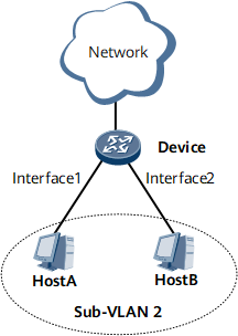
On the network shown in Figure 1, the device is connected to Host A and Host B. The interfaces connecting to Host A and Host B belong to the same sub-VLAN which is configured with Layer 2 port isolation. Therefore, Host A and Host B cannot communicate with each other at Layer 2. If Host A and Host B need to communicate with each other, enable intra-VLAN proxy ND on the device.

Configuration Roadmap
The configuration roadmap is as follows:
Create and configure a super-VLAN and a sub-VLAN.
Add interfaces to the sub-VLAN.
Create VLANIF interfaces for the super-VLAN and assign IPv6 addresses to the VLANIF interfaces.
Enable intra-VLAN proxy ND on the VLANIF interfaces in the super-VLAN.
Data Preparation
To complete the configuration, you need the following data:
IPv6 addresses of VLANIF interfaces
IPv6 addresses of Host A and Host B
Procedure
- Configure a super-VLAN and a sub-VLAN.
# Configure a sub-VLAN.
<HUAWEI> system-view
[~HUAWEI] sysname Device
[*HUAWEI] commit
[~Device] vlan 2
[*Device-vlan2] commit
[~Device-vlan2] quit
# Add interfaces to the sub-VLAN.
[~Device] interface gigabitethernet 0/1/1
[~Device-GigabitEthernet0/1/1] portswitch
[*Device-GigabitEthernet0/1/1] port default vlan 2
[*Device-GigabitEthernet0/1/1] port isolate-state enable vlan 2
[*Device-GigabitEthernet0/1/1] quit
[*Device] interface gigabitethernet 0/1/2
[*Device-GigabitEthernet0/1/2] portswitch
[*Device-GigabitEthernet0/1/2] port default vlan 2
[*Device-GigabitEthernet0/1/2] port isolate-state enable vlan 2
[*Device-GigabitEthernet0/1/2] quit
[*Device] commit
# Configure a super-VLAN, and add the sub-VLAN to the super-VLAN.
[~Device] vlan 3
[*Device-vlan3] aggregate-vlan
[*Device-vlan3] access-vlan 2
[*Device-vlan3] quit
[*Device] commit
- Create and configure VLANIF interfaces.
# Create VLANIF 3.
[~Device] interface Vlanif 3# Assign an IPv6 address to VLANIF 3.
[*Device-Vlanif3] ipv6 enable
[*Device-Vlanif3] ipv6 address 2001:db8:300:400::4 64
- Enable intra-VLAN proxy ND on the VLANIF interfaces.
[*Device-Vlanif3] ipv6 nd proxy inner-access-vlan enable
[*Device-Vlanif3] commit
- Configure the IPv6 addresses of hosts.
# Configure the IPv6 address of Host A as 2001:db8:300:400::1/64.
# Configure the IPv6 address of Host B as 2001:db8:300:400::3/64.
- Verify the configuration.
After the configurations are complete, Host A and Host B can ping each other.
Configuration Files
Device configuration file
#
sysname Device
#
vlan batch 2 to 3
#
vlan 3
 aggregate-vlan
 access-vlan 2
#
interface Vlanif3
 ipv6 enable
 ipv6 address 2001:DB8:300:400::4/64
 ipv6 nd proxy inner-access-vlan enable
#
interface GigabitEthernet0/1/1
 portswitch
 port default vlan 2
 port isolate-state enable vlan 2
#
interface GigabitEthernet0/1/2
 portswitch
 port default vlan 2
 port isolate-state enable vlan 2
#
return