Example for Configuring Inter-VLAN Proxy ND in a VLAN Aggregation Scenario
This section provides an example for configuring inter-VLAN proxy ND to allow devices in different VLANs to communicate with each other in a VLAN aggregation scenario.
Networking Requirements
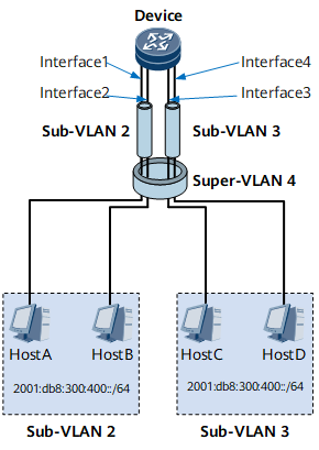
If hosts are on the same network segment and physical network but belong to different VLANs, inter-VLAN proxy ND must be enabled on the associated VLAN interfaces to enable Layer 3 interworking between the hosts.

Configuration Roadmap
The configuration roadmap is as follows:
Configure super-VLANs and sub-VLANs.
Add interfaces to the sub-VLAN.
Create VLANIF interfaces for the super-VLAN and assign IPv6 addresses to the VLANIF interfaces.
Enable inter-VLAN proxy ND.
Data Preparation
To complete the configuration, you need the following data:
IPv6 addresses of hosts in different VLANs
IDs of the sub-VLANs and super-VLANs
IPv6 addresses of the VLANIF interfaces in the super-VLAN
Procedure
- Configure super-VLANs and sub-VLANs.
# Configure sub-VLAN 2.
<HUAWEI> system-view
[~HUAWEI] sysname Device
[*HUAWEI] commit
[~Device] vlan 2
[*Device-vlan2] quit
[*Device] commit
# Add GE 0/1/1 and GE 0/1/2 to sub-VLAN 2.
[~Device] interface gigabitethernet 0/1/1
[~Device-GigabitEthernet0/1/1] portswitch
[*Device-GigabitEthernet0/1/1] port link-type access
[*Device-GigabitEthernet0/1/1] port default vlan 2
[*Device-GigabitEthernet0/1/1] quit
[*Device] interface gigabitethernet 0/1/2
[*Device-GigabitEthernet0/1/2] portswitch
[*Device-GigabitEthernet0/1/2] port link-type access
[*Device-GigabitEthernet0/1/2] port default vlan 2
[*Device-GigabitEthernet0/1/2] quit
[*Device] commit
# Configure sub-VLAN 3.
[~Device] vlan 3
[*Device-vlan3] quit
[*Device] commit
# Add GE 0/1/9 and GE 0/1/10 to sub-VLAN 3.
[~Device] interface gigabitethernet 0/1/9
[~Device-GigabitEthernet0/1/9] portswitch
[*Device-GigabitEthernet0/1/9] port link-type access
[**Device-GigabitEthernet0/1/9] port default vlan 3
[*Device-GigabitEthernet0/1/9] quit
[*Device] interface gigabitethernet 0/1/10
[*Device-GigabitEthernet0/1/10] portswitch
[*Device-GigabitEthernet0/1/10] port link-type access
[*Device-GigabitEthernet0/1/10] port default vlan 3
[*Device-GigabitEthernet0/1/10] quit
[*Device] commit
# Configure super-VLAN 4 and add sub-VLAN 2 and sub-VLAN 3 to super-VLAN 4.
[~Device] vlan 4
[*Device-vlan4] aggregate-vlan
[*Device-vlan4] access-vlan 2
[*Device-vlan4] access-vlan 3
[*Device-vlan4] quit
[*Device] commit
- Create and configure VLANIF 4.
# Create VLANIF 4.
[~Device] interface Vlanif 4# Assign an IPv6 address to VLANIF 4.
[*Device-Vlanif4] ipv6 enable
[*Device-Vlanif4] ipv6 address 2001:db8:300:400::5 64
- Enable inter-VLAN proxy ND on VLANIF 4.
[*Device-Vlanif4] ipv6 nd proxy inter-access-vlan enable
[*Device-Vlanif4] quit
[*Device] commit
- Configure the IPv6 addresses of hosts.
# Configure the IPv6 address of Host A as 2001:db8:300:400::1/64.
# Configure the IPv6 address of Host B as 2001:db8:300:400::2/64.
# Configure the IPv6 address of Host C as 2001:db8:300:400::3/64.
# Configure the IPv6 address of Host D as 2001:db8:300:400::4/64.
- Verify the configuration.
After the configurations are complete, the hosts in sub-VLAN 2 and sub-VLAN 3 can ping each other.
Configuration Files
Device configuration file
#
sysname Device
#
vlan batch 2 to 4
#
vlan 4
 aggregate-vlan
 access-vlan 2 to 3
#
interface Vlanif4
 ipv6 enable
 ipv6 address 2001:DB8:300:400::5/64
 ipv6 nd proxy inter-access-vlan enable
#
interface GigabitEthernet0/1/1
 portswitch
 undo shutdown
 port link-type access
 port default vlan 2
#
interface GigabitEthernet0/1/2
 portswitch
 undo shutdown
 port link-type access
 port default vlan 2
#
interface GigabitEthernet0/1/9
 portswitch
 undo shutdown
 port link-type access
 port default vlan 3
#
interface GigabitEthernet0/1/10
 portswitch
 undo shutdown
 port link-type access
 port default vlan 3
#
return