Example for Configuring Local Proxy ND
This section provides an example for configuring local proxy ND in a scenario where hosts are on the same network segment and BD but the BD is configured with user isolation.
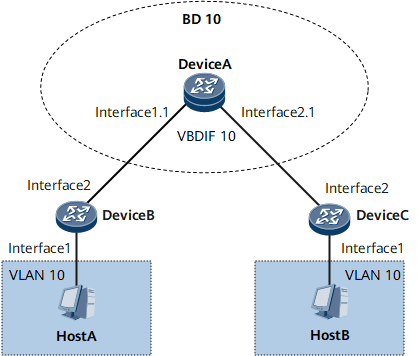
Networking Requirements
In the EVC model, the member interfaces of a BD broadcast the received packets in the BD. To reduce broadcast operations, network administrators usually configure split horizon on the member interfaces that do not need to intercommunicate to isolate these member interfaces.

Configuration Roadmap
The configuration roadmap is as follows:
Configure Layer 2 forwarding on DeviceB and DeviceC.
- Create a VLAN and add downstream interfaces to the VLAN.
- Configure Layer 2 forwarding on upstream interfaces so that the packets sent to DeviceA carry a single VLAN tag.
- Create an EVC model on DeviceA.
- Configure a BD for service forwarding.
- Create a Layer 2 sub-interface and add the sub-interface to the BD.
- Enable local proxy ND on DeviceA.
- Create a VBDIF interface and assign an IPv6 address to it.
- Enable local proxy ND to allow HostA and HostB to intercommunicate.
Data Preparation
To complete the configuration, you need the following data:
IPv6 addresses of interfaces
IPv6 addresses of hosts
Procedure
- Configure Layer 2 forwarding on DeviceB and DeviceC.
# Configure DeviceB.
<HUAWEI> system-view
[~HUAWEI] sysname DeviceB
[*HUAWEI] commit
[~DeviceB] vlan 10
[*DeviceB-vlan10] quit
[*DeviceB] interface gigabitethernet 0/1/1
[*DeviceB-GigabitEthernet0/1/1] portswitch
[*DeviceB-GigabitEthernet0/1/1] port link-type access
[*DeviceB-GigabitEthernet0/1/1] port default vlan 10
[*DeviceB-GigabitEthernet0/1/1] quit
[*DeviceB] interface gigabitethernet 0/1/2
[*DeviceB-GigabitEthernet0/1/2] portswitch
[*DeviceB-GigabitEthernet0/1/2] port link-type trunk
[*DeviceB-GigabitEthernet0/1/2] port trunk allow-pass vlan 10
[*DeviceB-GigabitEthernet0/1/2] commit
[~DeviceB-GigabitEthernet0/1/2] quit
Repeat this step for DeviceC. For configuration details, see Configuration Files in this section.
- Create an EVC model on DeviceA.
# Create a BD.
<HUAWEI> system-view
[~HUAWEI] sysname DeviceA
[*HUAWEI] commit
[~DeviceA] bridge-domain 10
[*DeviceA-bd10] split-horizon enable
[*DeviceA-bd10] quit
# Create a Layer 2 sub-interface and add the sub-interface to the BD.
[*DeviceA] interface gigabitethernet 0/1/1.1 mode l2
[*DeviceA-GigabitEthernet0/1/1.1] encapsulation dot1q vid 10
[*DeviceA-GigabitEthernet0/1/1.1] rewrite pop single
[*DeviceA-GigabitEthernet0/1/1.1] bridge-domain 10
[*DeviceA-GigabitEthernet0/1/1] quit
[*DeviceA] interface gigabitethernet 0/1/2.1 mode l2
[*DeviceA-GigabitEthernet0/1/2.1] encapsulation dot1q vid 10
[*DeviceA-GigabitEthernet0/1/2.1] rewrite pop single
[*DeviceA-GigabitEthernet0/1/2.1] bridge-domain 10
[*DeviceA-GigabitEthernet0/1/2.1] commit
[~DeviceA-GigabitEthernet0/1/2] quit
- Enable local proxy ND on DeviceA.
# Create a VBDIF interface and assign an IPv6 address to it.
[~DeviceA] interface Vbdif 10
[*DeviceA-Vbdif10] ipv6 enable
[*DeviceA-Vbdif10] ipv6 address 2001:db8:300:400::4 64
# Enable local proxy ND.
[*DeviceA-Vbdif10] ipv6 nd proxy local enable
[*DeviceA-Vbdif10] commit
- Configure the IPv6 addresses of hosts.
# Configure the IPv6 address of HostA as 2001:db8:300:400::1/64.
# Configure the IPv6 address of HostB as 2001:db8:300:400::3/64.
- Verify the configuration.
After the configurations are complete, HostA and HostB can ping each other.
Configuration Files
DeviceA configuration file
#
sysname DeviceA
#
bridge-domain 10
 split-horizon enable
#
interface Vbdif10
 ipv6 enable
 ipv6 address 2001:DB8:300:400::4/64
 ipv6 nd proxy local enable
#
interface GigabitEthernet0/1/1
#
interface GigabitEthernet0/1/1.1 mode l2
 encapsulation dot1q vid 10
 rewrite pop single
 bridge-domain 10
#
interface GigabitEthernet0/1/2
#
interface GigabitEthernet0/1/2.1 mode l2
 encapsulation dot1q vid 10
 rewrite pop single
 bridge-domain 10
#
return
DeviceB configuration file
#
sysname DeviceB
#
vlan batch 10
#
interface GigabitEthernet0/1/1
 portswitch
 port link-type access
 port default vlan 10
#
interface GigabitEthernet0/1/2
 portswitch
 port link-type trunk
 port trunk allow-pass vlan 10
#
return
DeviceC configuration file
#
sysname DeviceC
#
vlan batch 10
#
interface GigabitEthernet0/1/1
 portswitch
 port link-type access
 port default vlan 10
#
interface GigabitEthernet0/1/2
 portswitch
 port link-type trunk
 port trunk allow-pass vlan 10
#
return