Example for Configuring PBB VPLS with an E-Trunk Determining the Master/Backup NPE Status

This section provides an example for configuring PBB VPLS with an E-Trunk determining the master/backup NPE status.

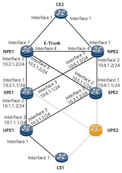
Networking Requirements

On the network shown in Figure 1, PBB VPLS needs to be configured for CE1 and CE2 to communicate, VPLS PW redundancy needs to be configured to determine the master/backup SPE status, and an E-Trunk needs to be configured to determine the master/backup NPE status.

Figure 1 Configuring PBB VPLS with an E-Trunk determining the master/backup NPE status
  • Interfaces 1 through 4 and sub-interface 1.1 in this example represent GE 0/1/0, GE 0/1/8, GE 0/1/16, GE 0/1/24, and GE 0/1/0.1, respectively.


Configuration Roadmap

The configuration roadmap is as follows:

  1. Configure an IP address and enable an IGP on each interface to ensure IP connectivity.
  2. Configure MPLS and MPLS LDP.
  3. Configure PBB VPLS.
  4. Configure an Eth-Trunk to determine the master/backup NPE status.
  5. Configure VPLS PW redundancy to determine the master/backup SPE status.

Data Preparation

  • IP addresses and masks of interfaces on the backbone network
  • I-VSI and B-VSI names, VSI IDs, B-SMAC addresses, B-DMAC addresses, and I-tags
  • E-Trunk ID, system ID, LACP priority, E-Trunk priority, local and peer IP addresses, and Eth-Trunk IDs ID

Procedure

  1. Configure interface IP addresses for each CE and PE in accordance with Configuration Files.
  2. Configure an IGP (OSPF in this example) on each PE.

    # Configure UPE1.

    <UPE1> system-view
    [~UPE1] ospf 1
    [*UPE1-ospf-1] area 0
    [*UPE1-ospf-1-area-0.0.0.0] network 1.1.1.1 0.0.0.0
    [*UPE1-ospf-1-area-0.0.0.0] network 10.1.1.0 0.0.0.255
    [*UPE1-ospf-1-area-0.0.0.0] network 10.3.1.0 0.0.0.255
    [*UPE1-ospf-1-area-0.0.0.0] quit
    [*UPE1-ospf-1] quit
    [*UPE1] commit

    # Configure SPE1.

    <SPE1> system-view
    [~SPE1] ospf 1
    [*SPE1-ospf-1] area 0
    [*SPE1-ospf-1-area-0.0.0.0] network 2.2.2.2 0.0.0.0
    [*SPE1-ospf-1-area-0.0.0.0] network 10.1.1.0 0.0.0.255
    [*SPE1-ospf-1-area-0.0.0.0] network 10.2.1.0 0.0.0.255
    [*SPE1-ospf-1-area-0.0.0.0] network 10.6.1.0 0.0.0.255
    [*SPE1-ospf-1-area-0.0.0.0] quit
    [*SPE1-ospf-1] quit
    [*SPE1] commit

    # Configure SPE2.

    <SPE2> system-view
    [~SPE2] ospf 1
    [*SPE2-ospf-1] area 0
    [*SPE2-ospf-1-area-0.0.0.0] network 4.4.4.4 0.0.0.0
    [*SPE2-ospf-1-area-0.0.0.0] network 10.3.1.0 0.0.0.255
    [*SPE2-ospf-1-area-0.0.0.0] network 10.4.1.0 0.0.0.255
    [*SPE2-ospf-1-area-0.0.0.0] network 10.5.1.0 0.0.0.255
    [*SPE2-ospf-1-area-0.0.0.0] quit
    [*SPE2-ospf-1] quit
    [*SPE2] commit

    # Configure NPE1.

    <NPE1> system-view
    [~NPE1] ospf 1
    [*NPE1-ospf-1] area 0
    [*NPE1-ospf-1-area-0.0.0.0] network 3.3.3.3 0.0.0.0
    [*NPE1-ospf-1-area-0.0.0.0] network 10.2.1.0 0.0.0.255
    [*NPE1-ospf-1-area-0.0.0.0] network 10.5.1.0 0.0.0.255
    [*NPE1-ospf-1-area-0.0.0.0] quit
    [*NPE1-ospf-1] quit
    [*NPE1] commit

    # Configure NPE2.

    <NPE2> system-view
    [~NPE2] ospf 1
    [*NPE2-ospf-1] area 0
    [*NPE2-ospf-1-area-0.0.0.0] network 5.5.5.5 0.0.0.0
    [*NPE2-ospf-1-area-0.0.0.0] network 10.4.1.0 0.0.0.255
    [*NPE2-ospf-1-area-0.0.0.0] network 10.6.1.0 0.0.0.255
    [*NPE2-ospf-1-area-0.0.0.0] quit
    [*NPE2-ospf-1] quit
    [*NPE2] commit

    After completing the configurations, check OSPF route information. The following example uses the command output on UPE1.

    [~UPE1] display ospf routing
     OSPF Process 1 with Router ID 10.1.1.1
       Routing Tables
    
     Routing for Network
     Destination        Cost     Type       NextHop         AdvRouter       Area           
     1.1.1.1/32         0        Direct     1.1.1.1         10.1.1.1        0.0.0.0 
     2.2.2.2/32         1        Stub       10.1.1.2        10.1.1.2        0.0.0.0 
     4.4.4.4/32         1        Stub       10.3.1.2        10.3.1.2        0.0.0.0 
     5.5.5.5/32         2        Stub       10.1.1.2        5.5.5.5         0.0.0.0 
     5.5.5.5/32         2        Stub       10.3.1.2        5.5.5.5         0.0.0.0 
     10.1.1.0/24        1        Direct     10.1.1.1        10.1.1.1        0.0.0.0 
     10.2.1.0/24        2        Transit    10.1.1.2        10.1.1.2        0.0.0.0 
     10.3.1.0/24        1        Direct     10.3.1.1        10.1.1.1        0.0.0.0 
     10.4.1.0/24        2        Transit    10.3.1.2        10.3.1.2        0.0.0.0 
     10.5.1.0/24        2        Transit    10.3.1.2        10.3.1.2        0.0.0.0 
     10.6.1.0/24        2        Transit    10.1.1.2        10.1.1.2        0.0.0.0 
    
     Total Nets: 11
     Intra Area: 11  Inter Area: 0  ASE: 0  NSSA: 0
    

  3. Configure MPLS and MPLS LDP and establish LSPs.

    # Configure UPE1.

    [~UPE1] mpls lsr-id 1.1.1.1
    [*UPE1] mpls
    [*UPE1-mpls] quit
    [*UPE1] mpls ldp
    [*UPE1-mpls-ldp] quit
    [*UPE1] interface gigabitethernet 0/1/8
    [*UPE1-GigabitEthernet0/1/8] mpls
    [*UPE1-GigabitEthernet0/1/8] mpls ldp
    [*UPE1-GigabitEthernet0/1/8] quit
    [*UPE1-mpls-ldp] quit
    [*UPE1] interface gigabitethernet 0/1/16
    [*UPE1-GigabitEthernet0/1/16] mpls
    [*UPE1-GigabitEthernet0/1/16] mpls ldp
    [*UPE1-GigabitEthernet0/1/16] quit
    [*UPE1] commit

    # Configure SPE1.

    [~SPE1] mpls lsr-id 2.2.2.2
    [*SPE1] mpls
    [*SPE1-mpls] quit
    [*SPE1] mpls ldp
    [*SPE1-mpls-ldp] quit
    [*SPE1] interface gigabitethernet 0/1/0
    [*SPE1-GigabitEthernet0/1/0] mpls
    [*SPE1-GigabitEthernet0/1/0] mpls ldp
    [*SPE1-GigabitEthernet0/1/0] quit
    [*SPE1-mpls-ldp] quit
    [*SPE1] interface gigabitethernet 0/1/8
    [*SPE1-GigabitEthernet0/1/8] mpls
    [*SPE1-GigabitEthernet0/1/8] mpls ldp
    [*SPE1-GigabitEthernet0/1/8] quit
    [*SPE1-mpls-ldp] quit
    [*SPE1] interface gigabitethernet 0/1/16
    [*SPE1-GigabitEthernet0/1/16] mpls
    [*SPE1-GigabitEthernet0/1/16] mpls ldp
    [*SPE1-GigabitEthernet0/1/16] quit
    [*SPE1] commit

    # Configure SPE2.

    [~SPE2] mpls lsr-id 4.4.4.4
    [*SPE2] mpls
    [*SPE2-mpls] quit
    [*SPE2] mpls ldp
    [*SPE2-mpls-ldp] quit
    [*SPE2] interface gigabitethernet 0/1/0
    [*SPE2-GigabitEthernet0/1/0] mpls
    [*SPE2-GigabitEthernet0/1/0] mpls ldp
    [*SPE2-GigabitEthernet0/1/0] quit
    [*SPE2-mpls-ldp] quit
    [*SPE2] interface gigabitethernet 0/1/8
    [*SPE2-GigabitEthernet0/1/8] mpls
    [*SPE2-GigabitEthernet0/1/8] mpls ldp
    [*SPE2-GigabitEthernet0/1/8] quit
    [*SPE2-mpls-ldp] quit
    [*SPE2] interface gigabitethernet 0/1/16
    [*SPE2-GigabitEthernet0/1/16] mpls
    [*SPE2-GigabitEthernet0/1/16] mpls ldp
    [*SPE2-GigabitEthernet0/1/16] quit
    [*SPE2] commit

    # Configure NPE1.

    [~NPE1] mpls lsr-id 3.3.3.3
    [*NPE1] mpls
    [*NPE1-mpls] quit
    [*NPE1] mpls ldp
    [*NPE1-mpls-ldp] quit
    [*NPE1] interface gigabitethernet 0/1/8
    [*NPE1-GigabitEthernet0/1/8] mpls
    [*NPE1-GigabitEthernet0/1/8] mpls ldp
    [*NPE1-GigabitEthernet0/1/8] quit
    [*NPE1-mpls-ldp] quit
    [*NPE1] interface gigabitethernet 0/1/16
    [*NPE1-GigabitEthernet0/1/16] mpls
    [*NPE1-GigabitEthernet0/1/16] mpls ldp
    [*NPE1-GigabitEthernet0/1/16] quit
    [*NPE1] commit

    # Configure NPE2.

    [~NPE2] mpls lsr-id 5.5.5.5
    [*NPE2] mpls
    [*NPE2-mpls] quit
    [*NPE2] mpls ldp
    [*NPE2-mpls-ldp] quit
    [*NPE2] interface gigabitethernet 0/1/8
    [*NPE2-GigabitEthernet0/1/8] mpls
    [*NPE2-GigabitEthernet0/1/8] mpls ldp
    [*NPE2-GigabitEthernet0/1/8] quit
    [*NPE2-mpls-ldp] quit
    [*NPE2] interface gigabitethernet 0/1/16
    [*NPE2-GigabitEthernet0/1/16] mpls
    [*NPE2-GigabitEthernet0/1/16] mpls ldp
    [*NPE2-GigabitEthernet0/1/16] quit
    [*NPE2] commit

    # After completing the configurations, check LDP LSP information. The following example uses the command output on UPE1.

    [~UPE1] display mpls ldp session
     LDP Session(s) in Public Network
     Codes: LAM(Label Advertisement Mode), SsnAge Unit(DDDD:HH:MM)
     An asterisk (*) before a session means the session is being deleted.
    --------------------------------------------------------------------------
     PeerID             Status      LAM  SsnRole  SsnAge       KASent/Rcv
    --------------------------------------------------------------------------
     2.2.2.2:0          Operational DU   Passive  0000:00:01   6/6
     4.4.4.4:0          Operational DU   Passive  0000:00:01   6/6
    --------------------------------------------------------------------------
    TOTAL: 2 Session(s) Found.TOTAL: 1 Session(s) Found.

  4. Configure PBB VPLS.
    1. Enable MPLS L2VPN.

      # Configure UPE1.

      [~UPE1] mpls l2vpn
      [*UPE1-l2vpn] quit
      [*UPE1] commit

      # Configure SPE1.

      [~SPE1] mpls l2vpn
      [*SPE1-l2vpn] quit
      [*SPE1] commit

      # Configure SPE2.

      [~SPE2] mpls l2vpn
      [*SPE2-l2vpn] quit
      [*SPE2] commit

      # Configure NPE1.

      [~NPE1] mpls l2vpn
      [*NPE1-l2vpn] quit
      [*NPE1] commit

      # Configure NPE2.

      [~NPE2] mpls l2vpn
      [*NPE2-l2vpn] quit
      [*NPE2] commit

    2. Configure I-VSIs.

      # Configure UPE1.

      [~UPE1] vsi ivsi1 i-vsi p2p
      [*UPE1-vsi-ivsi1] pwsignal ldp
      [*UPE1-vsi-ivsi1-ldp] vsi-id 10
      [*UPE1-vsi-ivsi1-ldp] quit
      [*UPE1-vsi-ivsi1] pbb i-tag 100
      [*UPE1-vsi-ivsi1] pbb backbone-destination-mac 00e0-fc12-3456 static
      [*UPE1-vsi-ivsi1] quit
      [*UPE1] commit

      # Configure NPE1.

      [~PE2] vsi ivsi1 i-vsi p2p
      [*NPE1-vsi-ivsi1] pwsignal ldp
      [*NPE1-vsi-ivsi1-ldp] vsi-id 10
      [*NPE1-vsi-ivsi1-ldp] mac-withdraw enable
      [*NPE1-vsi-ivsi1-ldp] interface-status-change mac-withdraw enable
      [*NPE1-vsi-ivsi1-ldp] quit
      [*NPE1-vsi-ivsi1] ignore-ac-state
      [*NPE1-vsi-ivsi1] pbb i-tag 100
      [*NPE1-vsi-ivsi1] pbb backbone-destination-mac 00e0-fc00-1234 static
      [*NPE1-vsi-ivsi1] quit
      [*NPE1] commit

      # Configure NPE2.

      [~NPE2] vsi ivsi1 i-vsi p2p
      [*NPE2-vsi-ivsi1] pwsignal ldp
      [*NPE2-vsi-ivsi1-ldp] vsi-id 10
      [*NPE2-vsi-ivsi1-ldp] mac-withdraw enable
      [*NPE2-vsi-ivsi1-ldp] interface-status-change mac-withdraw enable
      [*NPE2-vsi-ivsi1-ldp] quit
      [*NPE2-vsi-ivsi1] ignore-ac-state
      [*NPE2-vsi-ivsi1] pbb i-tag 100
      [*NPE2-vsi-ivsi1] pbb backbone-destination-mac 00e0-fc00-1234 static
      [*NPE2-vsi-ivsi1] quit
      [*NPE2] commit

    3. Configure B-VSIs and specify VPLS peers for these B-VSIs.

      # Configure UPE1.

      [~UPE1] vsi bvsi1 b-vsi
      [*UPE1-vsi-bvsi1] pwsignal ldp
      [*UPE1-vsi-bvsi1-ldp] vsi-id 100
      [*UPE1-vsi-bvsi1-ldp] peer 2.2.2.2
      [*UPE1-vsi-bvsi1-ldp] peer 4.4.4.4
      [*UPE1-vsi-bvsi1-ldp] quit
      [*UPE1-vsi-bvsi1] pbb backbone-source-mac 00e0-fc00-1234
      [*UPE1-vsi-bvsi1] pbb mac-withdraw mac-opt-compatible
      [*UPE1-vsi-bvsi1] quit
      [*UPE1] commit

      # Configure SPE1.

      [~SPE1] vsi bvsi1 b-vsi
      [*SPE1-vsi-bvsi1] pwsignal ldp
      [*SPE1-vsi-bvsi1-ldp] vsi-id 100
      [*SPE1-vsi-bvsi1-ldp] mac-withdraw enable
      [*SPE1-vsi-bvsi1-ldp] npe-upe mac-withdraw enable
      [*SPE1-vsi-bvsi1-ldp] upe-npe mac-withdraw enable
      [*SPE1-vsi-bvsi1-ldp] peer 1.1.1.1 upe
      [*SPE1-vsi-bvsi1-ldp] peer 3.3.3.3
      [*SPE1-vsi-bvsi1-ldp] peer 5.5.5.5
      [*SPE1-vsi-bvsi1-ldp] quit
      [*SPE1-vsi-bvsi1] quit
      [*SPE1] commit

      # Configure SPE2.

      [~SPE2] vsi bvsi1 b-vsi
      [*SPE2-vsi-bvsi1] pwsignal ldp
      [*SPE2-vsi-bvsi1-ldp] vsi-id 100
      [*SPE2-vsi-bvsi1-ldp] mac-withdraw enable
      [*SPE2-vsi-bvsi1-ldp] npe-upe mac-withdraw enable
      [*SPE2-vsi-bvsi1-ldp] upe-npe mac-withdraw enable
      [*SPE2-vsi-bvsi1-ldp] peer 1.1.1.1 upe
      [*SPE2-vsi-bvsi1-ldp] peer 3.3.3.3
      [*SPE2-vsi-bvsi1-ldp] peer 5.5.5.5
      [*SPE2-vsi-bvsi1-ldp] quit
      [*SPE2-vsi-bvsi1] quit
      [*SPE2] commit

      # Configure NPE1.

      [~NPE1] vsi bvsi1 b-vsi
      [*NPE1-vsi-bvsi1] pwsignal ldp
      [*NPE1-vsi-bvsi1-ldp] vsi-id 100
      [*NPE1-vsi-bvsi1-ldp] peer 2.2.2.2
      [*NPE1-vsi-bvsi1-ldp] peer 4.4.4.4
      [*NPE1-vsi-bvsi1-ldp] quit
      [*NPE1-vsi-bvsi1] pbb backbone-source-mac 00e0-fc12-3456
      [*NPE1-vsi-bvsi1] pbb mac-withdraw mac-opt-compatible
      [*NPE1-vsi-bvsi1] quit
      [*NPE1] commit

      # Configure NPE2.

      [~NPE2] vsi bvsi1 b-vsi
      [*NPE2-vsi-bvsi1] pwsignal ldp
      [*NPE2-vsi-bvsi1-ldp] vsi-id 100
      [*NPE2-vsi-bvsi1-ldp] peer 2.2.2.2
      [*NPE2-vsi-bvsi1-ldp] peer 4.4.4.4
      [*NPE2-vsi-bvsi1-ldp] quit
      [*NPE2-vsi-bvsi1] pbb backbone-source-mac 00e0-fc12-3456
      [*NPE2-vsi-bvsi1] pbb mac-withdraw mac-opt-compatible
      [*NPE2-vsi-bvsi1] quit
      [*NPE2] commit

    4. Bind the I-VSI on each PE to the B-VSI on that PE.

      # Configure UPE1.
      [~PE1] vsi ivsi1
      [*PE1-vsi-ivsi1] pbb binding b-vsi bvsi1
      [*PE1-vsi-ivsi1] quit
      [*PE1] commit
      # Configure NPE1.
      [~PE2] vsi ivsi1
      [*PE2-vsi-ivsi1] pbb binding b-vsi bvsi1
      [*PE2-vsi-ivsi1] quit
      [*PE2] commit
      # Configure NPE2.
      [~PE2] vsi ivsi1
      [*PE2-vsi-ivsi1] pbb binding b-vsi bvsi1
      [*PE2-vsi-ivsi1] quit
      [*PE2] commit

    5. Bind an AC interface to each I-VSI.

      # Configure UPE1.

      [*UPE1] interface gigabitethernet 0/1/0.1
      [*UPE1-Eth-Trunk10.1] vlan-type dot1q 10
      [*UPE1-Eth-Trunk10.1] l2 binding vsi ivsi1
      [*UPE1-Eth-Trunk10.1] quit
      [*UPE1] commit

      # Configure NPE1.

      [*NPE1] interface eth-trunk 10
      [*NPE1-Eth-Trunk10] mode lacp-static
      [*NPE1-Eth-Trunk10] trunkport gigabitethernet 0/1/0
      [*NPE1-Eth-Trunk10] quit
      [*NPE1] interface eth-trunk 10.1
      [*NPE1-Eth-Trunk10.1] vlan-type dot1q 10
      [*NPE1-Eth-Trunk10.1] l2 binding vsi ivsi1
      [*NPE1-Eth-Trunk10.1] quit
      [*NPE1] commit

      # Configure NPE2.

      [*NPE2] interface eth-trunk 10
      [*NPE2-Eth-Trunk10] mode lacp-static
      [*NPE2-Eth-Trunk10] trunkport gigabitethernet 0/1/0
      [*NPE2-Eth-Trunk10] quit
      [*NPE2] interface eth-trunk 10.1
      [*NPE2-Eth-Trunk10.1] vlan-type dot1q 10
      [*NPE2-Eth-Trunk10.1] l2 binding vsi ivsi1
      [*NPE2-Eth-Trunk10.1] quit
      [*NPE2] commit

      # After completing the configurations, check I-VSI and B-VSI information. The following example uses the command output on UPE1.

      [~UPE1] display vsi
      Total VSI number is 2, 2 is up, 0 is down, 2 is LDP mode, 0 is BGP mode, 0 is BGPAD mode, 0 is mixed mode, 0 is unspecified mode
      --------------------------------------------------------------------------
      Vsi                             Mem    PW    Mac       Encap     Mtu   Vsi
      Name                            Disc   Type  Learn     Type      Value State
      --------------------------------------------------------------------------
      bvsi1                           --     ldp   unqualify vlan      1500  up   
      ivsi1                           --     ldp   unqualify vlan      1500  up   
      

  5. Configure VPLS PW redundancy to determine the master/backup SPE status.

    [~UPE] vsi bvsi1
    [*UPE-vsi-bvsi1] vsi bvsi1
    [*UPE-vsi-bvsi1] protect-group bvsi1
    [*UPE-vsi-bvsi1-protect-group-bvsi1] protect-mode pw-redundancy master
    [*UPE-vsi-bvsi1-protect-group-bvsi1] reroute delay 60
    [*UPE-vsi-bvsi1-protect-group-bvsi1] peer 2.2.2.2 preference 1
    [*UPE-vsi-bvsi1-protect-group-bvsi1] peer 3.3.3.3 preference 2
    [*UPE-vsi-bvsi1-protect-group-bvsi1] quit
    [*UPE-vsi-bvsi1] quit
    [*UPE] commit

  6. Configure an E-Trunk to determine the master/backup NPE status.
    1. Configure Layer 2 forwarding on CE2.

      [~CE2] interface eth-trunk 10
      [*CE2-Eth-Trunk10] portswitch
      [*CE2-Eth-Trunk10] quit
      [*CE2] vlan 10
      [*CE2-vlan10] quit
      [*CE2] interface eth-trunk 10
      [*CE2-Eth-Trunk10] port trunk allow-pass vlan 10
      [*CE2-Eth-Trunk10] mode lacp-static
      [*CE2-Eth-Trunk10] quit
      [*CE2] commit

      # Add member interfaces to the Eth-Trunk interface.

      [~CE2] interface gigabitethernet 0/1/0
      [*CE2-GigabitEthernet0/1/0] eth-trunk 10
      [*CE2-GigabitEthernet0/1/0] quit
      [*CE2]interface gigabitethernet 0/1/8
      [*CE2-GigabitEthernet0/1/8] eth-trunk 10
      [*CE2-GigabitEthernet0/1/8] quit
      [*CE2] commit

    2. Configure the Eth-Trunk to work in static LACP mode on NPE1 and NPE2 and add member interfaces to the Eth-Trunk.

      # Configure NPE1.

      [~NPE1] interface eth-trunk 10
      [*NPE1-Eth-Trunk10] mode lacp-static
      [*NPE1-Eth-Trunk10] quit
      [*NPE1] interface gigabitethernet 0/1/0
      [*NPE1-GigabitEthernet0/1/0] eth-trunk 10
      [*NPE1-GigabitEthernet0/1/0] quit
      [*NPE1] commit

      # Configure NPE2.

      [~NPE2] interface eth-trunk 10
      [*NPE2-Eth-Trunk10] mode lacp-static
      [*NPE2-Eth-Trunk10] quit
      [*NPE2] interface gigabitethernet 0/1/0
      [*NPE2-GigabitEthernet0/1/0] eth-trunk 10
      [*NPE2-GigabitEthernet0/1/0] quit
      [*NPE2] commit

    3. Create an E-Trunk and add the Eth-Trunk to the E-Trunk.

      # Configure NPE1.

      [~NPE1] e-trunk 1
      [*NPE1-e-trunk-1] quit
      [*NPE1] interface eth-trunk 10
      [*NPE1-Eth-Trunk10] e-trunk 1
      [*NPE1-Eth-Trunk10] quit
      [*NPE1] commit

      # Configure NPE2.

      [~NPE2] e-trunk 1
      [*NPE2-e-trunk-1] quit
      [*NPE2] interface eth-trunk 10
      [*NPE2-Eth-Trunk10] e-trunk 1
      [*NPE2-Eth-Trunk10] quit
      [*NPE2] commit

    4. Configure E-Trunk attributes, including the E-Trunk priority, LACP priority, and system ID.

      # Configure NPE1.

      [~NPE1] e-trunk 1
      [*NPE1-e-trunk-1] priority 10
      [*NPE1-e-trunk-1] quit
      [*NPE1] lacp e-trunk priority 1
      [*NPE1] lacp e-trunk system-id 00e0-fc00-5566

      # Configure NPE2.

      [~NPE2] e-trunk 1
      [*NPE2-e-trunk-1] priority 20
      [*NPE2-e-trunk-1] quit
      [*NPE2] lacp e-trunk priority 1
      [*NPE2] lacp e-trunk system-id 00e0-fc00-5566

    5. Configure local and peer IP addresses for the E-Trunk.

      # Configure NPE1.

      [~NPE1] e-trunk 1
      [*NPE1-e-trunk-1] peer-address 5.5.5.5 source-address 3.3.3.3
      [*NPE1-e-trunk-1] quit
      [*NPE11] commit

      # Configure NPE2.

      [~NPE2] e-trunk 1
      [*NPE2-e-trunk-1] peer-address 3.3.3.3 source-address 5.5.5.5
      [*NPE2-e-trunk-1] commit

      # Verify the configuration. Run the display e-trunk command on NPE1. The command output shows that the NPE1 status is Master, and the interface status is Up.

      [~NPE1] display e-trunk  1
                                  The E-Trunk information
      E-TRUNK-ID : 1                          Revert-Delay-Time (s) : 120
      Priority : 50                           System-ID : 00e0-fc00-1122
      Peer-IP : 5.5.5.5                       Source-IP : 4.4.4.4
      State : Master                         Causation : PRI
      Send-Period (100ms) : 10                Fail-Time (100ms) : 200    
      Receive : 5689                          Send : 5695   
      RecDrop : 0                             SndDrop : 0   
      Peer-Priority : 20                      Peer-System-ID : 00e0-fc00-3344
      Peer-Fail-Time (100ms) : 200            BFD-Session : 1
      --------------------------------------------------------------------------------
                                  The Member information
      Type        ID  LocalPhyState  Work-Mode     State   Causation          Remote-ID
      Eth-Trunk   10  Up            auto          Master  PEER_MEMBER_DOWN   10 

    6. Bind a BFD session to the E-Trunk.

      # Configure NPE1.

      [~NPE1] bfd
      [*NPE1-bfd] quit
      [*NPE1] bfd hello bind peer-ip 5.5.5.5 source-ip 3.3.3.3
      [*NPE1-bfd-session-hello] discriminator local 1
      [*NPE1-bfd-session-hello] discriminator remote 2
      [*NPE1-bfd-session-hello] quit
      [*NPE1] e-trunk 1
      [*NPE1-e-trunk-1] e-trunk track bfd-session session-name hello
      [*NPE1-e-trunk-1] quit
      [*NPE1] commit

      # Configure NPE2.

      [~NPE2] bfd
      [*NPE2-bfd] quit
      [*NPE2] bfd hello bind peer-ip 3.3.3.3 source-ip 5.5.5.5
      [*NPE2-bfd-session-hello] discriminator local 2
      [*NPE2-bfd-session-hello] discriminator remote 1
      [*NPE2-bfd-session-hello] quit
      [*NPE2] e-trunk 1
      [*NPE2-e-trunk-1] e-trunk track bfd-session session-name hello
      [*NPE2-e-trunk-1] quit
      [*NPE2] commit

  7. Configure CE1 and CE2 to access PEs.

    # Configure CE1.

    [~CE1] interface gigabitethernet 0/1/0.1
    [*CE1-GigabitEthernet0/1/0.1] vlan-type dot1q 10
    [*CE1-GigabitEthernet0/1/0.1] ip address 10.10.1.1 24
    [*CE1-GigabitEthernet0/1/0.1] quit
    [*CE1] commit

    # Configure CE2.

    [~CE2] interface vlanif 10
    [*CE2-Vlanif10] ip address 10.10.1.2 24
    [*CE2-Vlanif10] quit
    [*CE2] commit

  8. Verify the configuration.

    After the configurations are complete, CE1 and CE2 can ping each other. The following uses the command output on CE1.

    [~CE1] ping 10.10.1.2
    PING 10.10.1.2: 56  data bytes, press CTRL_C to break
        Reply from 10.10.1.2: bytes=56 Sequence=1 ttl=255 time=3 ms
        Reply from 10.10.1.2: bytes=56 Sequence=2 ttl=255 time=1 ms
        Reply from 10.10.1.2: bytes=56 Sequence=3 ttl=255 time=2 ms
        Reply from 10.10.1.2: bytes=56 Sequence=4 ttl=255 time=1 ms
        Reply from 10.10.1.2: bytes=56 Sequence=5 ttl=255 time=2 ms
    
      --- 10.10.1.2 ping statistics ---
        5 packet(s) transmitted
        5 packet(s) received
        0.00% packet loss
        round-trip min/avg/max = 1/1/3 ms

Configuration Files

  • CE1 configuration file

    #
    sysname CE1
    #
    interface GigabitEthernet0/1/0
     undo shutdown
    #
    interface GigabitEthernet0/1/0.1
     vlan-type dot1q 10
     ip address 10.10.1.1 255.255.255.0
    #
    return
  • UPE1 configuration file

    #
    sysname UPE1
    #
    mpls lsr-id 1.1.1.1
    #
    mpls
    #
    mpls l2vpn
    #
    vsi bvsi1 b-vsi
     pwsignal ldp
      vsi-id 100
      peer 2.2.2.2
      peer 4.4.4.4
      protect-group bwanxixianzotect-mode pw-redundancy master
       reroute delay 60
       peer 2.2.2.2 preference 1
       peer 3.3.3.3 preference 2
     pbb backbone-source-mac 00e0-fc00-1234
     pbb mac-withdraw mac-opt-compatible
    #
    vsi ivsi1 i-vsi p2p
     pwsignal ldp
      vsi-id 10
     pbb i-tag 100
     pbb backbone-destination-mac 00e0-fc12-3456 static
     pbb binding b-vsi bvsi1
    #
    mpls ldp  
    #
    interface GigabitEthernet0/1/0
     undo shutdown
    #
    interface GigabitEthernet0/1/0.1
     vlan-type dot1q 10
     l2 binding vsi ivsi1 
    #
    interface GigabitEthernet0/1/8
     undo shutdown
     ip address 10.1.1.1 255.255.255.0
     mpls
     mpls ldp
    #
    interface GigabitEthernet0/1/16
     undo shutdown
     ip address 10.3.1.1 255.255.255.0
     mpls
     mpls ldp
    #
    interface LoopBack0
     ip address 1.1.1.1 255.255.255.255
    #
    ospf 1
     area 0.0.0.0
      network 1.1.1.1 0.0.0.0
      network 10.1.1.0 0.0.0.255
      network 10.3.1.0 0.0.0.255
    #
    return 
  • SPE1 configuration file

    #
    sysname SPE1
    #
    mpls lsr-id 2.2.2.2
    # 
    mpls
    #
    mpls l2vpn
    #
    vsi bvsi1 b-vsi
     pwsignal ldp
      vsi-id 100
      mac-withdraw enable
      npe-upe mac-withdraw enable
      upe-npe mac-withdraw enable
      peer 1.1.1.1 upe
      peer 3.3.3.3
      peer 5.5.5.5
    #
    mpls ldp  
    #
    interface GigabitEthernet0/1/0
     undo shutdown
     ip address 10.2.1.1 255.255.255.0
     mpls
     mpls ldp 
    #
    interface GigabitEthernet0/1/8
     undo shutdown
     ip address 10.1.1.2 255.255.255.0
     mpls
     mpls ldp 
    #
    interface GigabitEthernet0/1/16
     undo shutdown
     ip address 10.6.1.1 255.255.255.0
     mpls
     mpls ldp 
    #
    interface LoopBack0
     ip address 2.2.2.2 255.255.255.255
    #
    ospf 1
     area 0.0.0.0
      network 2.2.2.2 0.0.0.0
      network 10.1.1.0 0.0.0.255
      network 10.2.1.0 0.0.0.255
      network 10.6.1.0 0.0.0.255
    #
    return    
  • SPE2 configuration file

    #
    sysname SPE2
    #
    mpls lsr-id 3.3.3.3
    # 
    mpls
    #
    mpls l2vpn
    #
    vsi bvsi1 b-vsi
     pwsignal ldp
      vsi-id 100  
      mac-withdraw enable
      npe-upe mac-withdraw enable
      upe-npe mac-withdraw enable
      peer 1.1.1.1 upe
      peer 3.3.3.3
      peer 5.5.5.5
    #
    mpls ldp  
    #
    interface GigabitEthernet0/1/0
     undo shutdown
     ip address 10.4.1.1 255.255.255.0
     mpls
     mpls ldp 
    #
    interface GigabitEthernet0/1/8
     undo shutdown
     ip address 10.5.1.1 255.255.255.0
     mpls
     mpls ldp 
    #
    interface GigabitEthernet0/1/16
     undo shutdown
     ip address 10.3.1.2 255.255.255.0
     mpls
     mpls ldp 
    #
    interface LoopBack0
     ip address 3.3.3.3 255.255.255.255
    #
    ospf 1 
     area 0.0.0.0   
      network 4.4.4.4 0.0.0.0
      network 10.3.1.0 0.0.0.255
      network 10.4.1.0 0.0.0.255
      network 10.5.1.0 0.0.0.255
    #
    return    
  • NPE1 configuration file

    #
    sysname NPE1
    #
    lacp e-trunk system-id 00e0-fc00-5566
    lacp e-trunk priority 1
    #
    e-trunk 1
    #
    bfd
    #
    mpls lsr-id 3.3.3.3
    # 
    mpls
    #
    mpls l2vpn
    #
    e-trunk 1
     priority 10
     peer-address 5.5.5.5 source-address 3.3.3.3
     e-trunk track bfd-session session-name hello
    #
    vsi bvsi1 b-vsi
     pwsignal ldp
      vsi-id 10
      peer 2.2.2.2
      peer 4.4.4.4
     pbb backbone-source-mac 00e0-fc12-3456
     pbb mac-withdraw mac-opt-compatible
    #
    vsi ivsi1 i-vsi p2p
     pwsignal ldp
      vsi-id 10
     pbb i-tag 100
     pbb backbone-destination-mac 00e0-fc00-1234 static
     pbb binding b-vsi bvsi1
    #
    mpls ldp  
    #
    interface Eth-Trunk10
     mode lacp-static
     e-trunk 1
    #
    interface Eth-Trunk10.1
     vlan-type dot1q 10
     l2 binding vsi ivsi1 
    #
    interface GigabitEthernet0/1/0
     undo shutdown
     eth-trunk 10
    #
    interface GigabitEthernet0/1/8
     undo shutdown
     ip address 10.2.1.2 255.255.255.0
     mpls
     mpls ldp 
    #
    interface GigabitEthernet0/1/16
     undo shutdown
     ip address 10.5.1.2 255.255.255.0
     mpls
     mpls ldp 
    interface GigabitEthernet0/1/24
     undo shutdown
     mpls
     mpls ldp 
    #
    interface LoopBack0
     ip address 3.3.3.3 255.255.255.255
    #
    bfd hello bind peer-ip 5.5.5.5 source-ip 3.3.3.3
     discriminator local 1
     discriminator remote 2
    #
    ospf 1 
     area 0.0.0.0
      network 3.3.3.3 0.0.0.0
      network 10.2.1.0 0.0.0.255
      network 10.5.1.0 0.0.0.255
    #
    return    
  • NPE2 configuration file

    #
    sysname NPE2
    #
    lacp e-trunk system-id 00e0-fc00-5566
    lacp e-trunk priority 1
    #
    e-trunk 1
    #
    bfd
    #
    mpls lsr-id 5.5.5.5
    # 
    mpls
    #
    mpls l2vpn
    #
    vsi bvsi1 b-vsi
     pwsignal ldp
      vsi-id 100  
      peer 2.2.2.2
      peer 4.4.4.4
     pbb backbone-source-mac 00e0-fc12-3456
     pbb mac-withdraw mac-opt-compatible
    #
    vsi ivsi1 i-vsi p2p
     pwsignal ldp
      vsi-id 10
     pbb i-tag 100
     pbb backbone-destination-mac 00e0-fc00-1234 static
     pbb binding b-vsi bvsi1 
    #
    mpls ldp
    #
    e-trunk 1
     priority 20
     peer-address 4.4.4.4 source-address 5.5.5.5 
     e-trunk track bfd-session session-name hello
    #
    interface Eth-Trunk10
     mode lacp-static
     e-trunk 1
    #
    interface Eth-Trunk10.1
     vlan-type dot1q 10
     l2 binding vsi ivsi1
    #
    interface GigabitEthernet0/1/0
     undo shutdown
     eth-trunk 10
    #
    interface GigabitEthernet0/1/8
     undo shutdown
     ip address 10.4.1.2 255.255.255.0
     mpls
     mpls ldp
    #
    interface GigabitEthernet0/1/16
     undo shutdown
     ip address 10.6.1.2 255.255.255.0
     mpls
     mpls ldp
    #
    interface GigabitEthernet0/1/24
     undo shutdown
     mpls
     mpls ldp
    #
    interface LoopBack0
     ip address 5.5.5.5 255.255.255.255
    #
    bfd hello bind peer-ip 3.3.3.3 source-ip 5.5.5.5
     discriminator local 2
     discriminator remote 1
    #
    ospf 1 
     area 0.0.0.0   
      network 5.5.5.5 0.0.0.0
      network 10.4.1.0 0.0.0.255
      network 10.6.1.0 0.0.0.255
    #
    return
  • CE2 configuration file

    #
    sysname CE2
    #
    vlan batch 10
    #
    interface Vlanif10
     ip address 10.10.1.2 255.255.255.0 
    #
    interface Eth-Trunk10
     portswitch  
     port trunk allow-pass vlan 10
     mode lacp-static
    #
    interface GigabitEthernet0/1/0
     undo shutdown
     eth-trunk 10
    #
    interface GigabitEthernet0/1/8
     undo shutdown
     eth-trunk 10
    #
    return
Copyright © Huawei Technologies Co., Ltd.
< Previous topic Next topic >