Example for Configuring a Dot1q VLAN Tag Termination Sub-Interface to Support Proxy ARP
This example shows how to configure a dot1q VLAN tag termination sub-interface to support proxy ARP, and how to enable the interworking between users who are on the same network segment but different VLANs.
Networking Requirements
A range of VLANs can connect to a network segment using VLAN tag termination sub-interfaces. However, if users on the same network segment belong to different VLANs, these users cannot communicate at Layer 2, and rely on IP forwarding at Layer 3 to communicate with each other. You can configure VLAN tag termination sub-interfaces to support proxy ARP so that users from different VLANs can communicate.
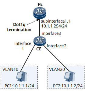
On the network shown in Figure 1, the PE connects to the CE through an Ethernet sub-interface; the CE connects to both PC1 and PC2. PC1 and PC2 belong to the same network segment but are on different VLANs. PC1 and PC2 have no default gateway. In this situation, you can configure GE 0/1/1.1 on the PE as a dot1q VLAN tag termination sub-interface and enable proxy ARP on the sub-interface so that PC1 and PC2 can communicate.

Configuration Roadmap
The configuration roadmap is as follows:
Create VLANs on the CE and determine the VLANs to which users belong.
Configure the Layer 2 forwarding function on the CE and allows packets from user VLANs to pass through.
Configure a dot1q VLAN tag termination sub-interface and enable proxy ARP on the sub-interface on the PE so that users from different VLANs can communicate.
Data Preparation
To complete the configuration, you need the following data:
- User VLAN IDs
- User IP addresses
- Names of interfaces that connect the PE and the CE
- Names of interfaces that connect the CE to PCs
Procedure
- Create a VLAN on the CE and associate a Layer 2 interface with the VLAN.
<HUAWEI> system-view
[~HUAWEI] sysname CE
[*HUAWEI] commit
[~CE] vlan batch 10 20
[*CE] interface gigabitethernet 0/1/1
[*CE-GigabitEthernet0/1/1] portswitch
[*CE-GigabitEthernet0/1/1] undo shutdown
[*CE-GigabitEthernet0/1/1] port link-type access
[*CE-GigabitEthernet0/1/1] port default vlan 10
[*CE-GigabitEthernet0/1/1] quit
[*CE] interface gigabitethernet 0/1/2
[*CE-GigabitEthernet0/1/2] portswitch
[*CE-GigabitEthernet0/1/2] undo shutdown
[*CE-GigabitEthernet0/1/2] port link-type access
[*CE-GigabitEthernet0/1/2] port default vlan 20
[*CE-GigabitEthernet0/1/2] quit
[*CE] commit
- Configure Layer 2 forwarding on the CE.
[~CE] interface gigabitethernet 0/1/3
[*CE-GigabitEthernet0/1/3] portswitch
[*CE-GigabitEthernet0/1/3] undo shutdown
[*CE-GigabitEthernet0/1/3] port link-type trunk
[*CE-GigabitEthernet0/1/3] port trunk allow-pass vlan 10 20
[*CE-GigabitEthernet0/1/3] quit
[*CE] commit
- Configure a dot1q VLAN tag termination sub-interface and enable proxy ARP on the sub-interface on the PE.
<HUAWEI> system-view
[~HUAWEI] sysname PE
[*HUAWEI] commit
[~PE] interface gigabitethernet 0/1/1
[*PE-GigabitEthernet0/1/1] undo shutdown
[*PE] interface gigabitethernet 0/1/1.1
[*PE-GigabitEthernet0/1/1.1] control-vid 1 dot1q-termination
[*PE-GigabitEthernet0/1/1.1] dot1q termination vid 10
[*PE-GigabitEthernet0/1/1.1] dot1q termination vid 20
[*PE-GigabitEthernet0/1/1.1] ip address 10.1.1.254 24
[*PE-GigabitEthernet0/1/1.1] arp-proxy inter-sub-vlan-proxy enable
[*PE-GigabitEthernet0/1/1.1] arp broadcast enable
[*PE-GigabitEthernet0/1/1.1] quit
[*PE] commit
- Verify the configuration.
Verify that PC1 can ping PC2.
Check the ARP table on PC1. If the MAC address of PC2 is the MAC address of GE 0/1/1 on the PE, the configuration is correct.
Configuration Files
PE configuration file
#
 sysname PE
#
interface GigabitEthernet0/1/1
 undo shutdown
interface GigabitEthernet0/1/1.1
 encapsulation dot1q-termination
 dot1q termination vid 10
 dot1q termination vid 20
 ip address 10.1.1.254 255.255.255.0
 arp-proxy inter-sub-vlan-proxy enable
 arp broadcast enable
#
return
CE configuration file
#
 sysname CE
#
 vlan batch 10 20
#
interface GigabitEthernet0/1/1
 portswitch
 undo shutdown
 port link-type access
 port default vlan 10
#
interface GigabitEthernet0/1/2
 portswitch
 undo shutdown
 port link-type access
 port default vlan 20
#
interface GigabitEthernet0/1/3
 portswitch
 undo shutdown
 port link-type trunk
 port trunk allow-pass vlan 10 20
#
return