Example for Configuring QinQ-based VLAN Tag Swapping for VPLS Access
After QinQ-based VLAN tag swapping is configured on an interface, the interface swaps the inner and outer virtual local area network (VLAN) tags carried in double-tagged packets when receiving them. This configuration does not take effect on single-tagged packets.
Networking Requirements
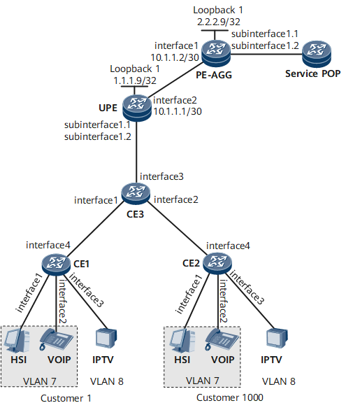
On the network shown in Figure 1, customers 1 to 1000 have three types of services: unicast high-speed Internet (HSI) services, unicast Voice over Internet Protocol (VoIP) services, and multicast Internet Protocol television (IPTV) services.
When customers 1 to 1000 send both unicast and multicast services, CE1 and CE2 add to packets inner VLAN tags indicating the services, and the CE3 adds to packets outer VLAN tags indicating the users. QinQ-based VLAN tag swapping needs to be configured on the user-end provider edge (UPE) to swap the inner and outer VLAN tags in double-tagged packets. As such, the outer tags in the packets indicate the services, and the inner tags indicate the users.
QinQ VLAN tag termination sub-interfaces are created on the UPE based on double VLAN tags in packets from the CE3, and the UPE provides virtual private LAN service (VPLS) access to services through these sub-interfaces.
Provide VPLS access for unicast services.
Create subinterface 1 on the UPE to provide VPLS access for HSI and VoIP services (in service VLAN 7) and configure subinterface 1 as a QinQ VLAN tag termination sub-interface in symmetrical mode to terminate the outer VLAN tags of packets. The inner VLAN tags of packets are transparently transmitted to the provider edge-access aggregation gateway (PE-AGG).
Configure subinterface 1 on the PE-AGG as a QinQ VLAN tag termination sub-interface in symmetrical mode. After receiving packets from the UPE, subinterface 1 adds a VLAN tag to each packet and forwards the packets to the Service point of presence (POP).
Provide VPLS access for multicast services.
Create subinterface 2 on the UPE to provide VPLS access for IPTV services (in service VLAN 8) and configure subinterface 2 as a QinQ VLAN tag termination sub-interface in asymmetrical mode to terminate the inner and outer VLAN tags of packets.
Configure subinterface 2 on the PE-AGG as a QinQ VLAN tag termination sub-interface in asymmetrical mode. After receiving packets from the UPE, subinterface 2 adds the service VLAN 8 to the packets and forwards the packets to the Service POP.
Configuration Roadmap
The configuration roadmap is as follows:
- Configure QinQ on the CE3 so that each packet received by the UPE carries two VLAN tags.
- Configure an Interior Gateway Protocol (IGP) on the Multiprotocol Label Switching (MPLS) backbone network.
- Enable basic MPLS functions and Label Distribution Protocol (LDP) on the MPLS backbone network.
- Enable MPLS Layer 2 virtual private network (L2VPN).
- Create virtual switching instances (VSIs) and specify LDP as the signaling protocol of the VSIs.
- Configure VLAN tag swapping and QinQ VLAN tag termination sub-interfaces, and bind the AC interfaces to the VSIs.
- Enable Internet Group Management Protocol (IGMP) snooping and configure the static router interface and querier.
Data Preparation
To complete the configuration, you need the following data:
IDs of inner VLAN tags that CE1 and CE2 add to packets to distinguish services
IDs of outer VLAN tags that the CE3 adds to packets to distinguish users
IP address of each interface
VSI ID (which is the same on the UPE and PE-AGG)
MPLS LSR IDs on the UPE and PE-AGG
VSI names on the UPE and PE-AGG
Names of interfaces bound to the VSIs
Procedure
- Configure QinQ so that the CE3 sends double-tagged packets to the UPE.
Switch Layer 3 interfaces to Layer 2 interfaces.

If the interface is a Layer 2 interface, skip this step.
# Configure CE1.
<*HUAWEI> system-view
[~HUAWEI] sysname CE1
[*HUAWEI] commit
[~CE1] interface gigabitethernet 0/1/1
[*CE1-GigabitEthernet0/1/1] portswitch
[*CE1-GigabitEthernet0/1/1] undo shutdown
[*CE1-GigabitEthernet0/1/1] quit
[*CE1] interface gigabitethernet 0/1/2
[*CE1-GigabitEthernet0/1/2] portswitch
[*CE1-GigabitEthernet0/1/2] undo shutdown
[*CE1-GigabitEthernet0/1/2] quit
[*CE1] interface gigabitethernet 0/1/3
[*CE1-GigabitEthernet0/1/3] portswitch
[*CE1-GigabitEthernet0/1/3] undo shutdown
[*CE1-GigabitEthernet0/1/3] quit
[*CE1] interface gigabitethernet 0/1/4
[*CE1-GigabitEthernet0/1/4] portswitch
[*CE1-GigabitEthernet0/1/4] undo shutdown
[*CE1-GigabitEthernet0/1/4] commit
[~CE1-GigabitEthernet0/1/4] quit
The configurations on CE2 are the same as those on CE1. For details, see "Configuration Files."
# Configure CE3.
<*HUAWEI> system-view
[~HUAWEI] sysname CE3
[*HUAWEI] commit
[~CE3] interface gigabitethernet 0/1/1
[*CE3-GigabitEthernet0/1/1] portswitch
[*CE3-GigabitEthernet0/1/1] undo shutdown
[*CE3-GigabitEthernet0/1/1] quit
[*CE3] interface gigabitethernet 0/1/2
[*CE3-GigabitEthernet0/1/2] portswitch
[*CE3-GigabitEthernet0/1/2] undo shutdown
[*CE3-GigabitEthernet0/1/2] quit
[*CE3] interface gigabitethernet 0/1/3
[*CE3-GigabitEthernet0/1/3] portswitch
[*CE3-GigabitEthernet0/1/3] undo shutdown
[*CE3-GigabitEthernet0/1/3] commit
[~CE3-GigabitEthernet0/1/3] quit
Configure QinQ.
# Configure CE1.
[*CE1] vlan 7
[*CE1-vlan7] port gigabitethernet 0/1/1
[*CE1-vlan7] port gigabitethernet 0/1/2
[*CE1-vlan7] quit
[*CE1] vlan 8
[*CE1-vlan8] port gigabitethernet 0/1/3
[*CE1-vlan8] quit
[*CE1] interface gigabitethernet 0/1/4
[*CE1-GigabitEthernet0/1/4] port trunk allow-pass vlan 7 8
[*CE1-GigabitEthernet0/1/4] undo shutdown
[*CE1-GigabitEthernet0/1/4] commit
[~CE1-GigabitEthernet0/1/4] quit
The configurations on CE2 are the same as those on CE1. For details, see "Configuration Files."
# Configure CE3.
[*CE3] vlan batch 1 to 1000
[*CE3] interface gigabitethernet 0/1/1
[*CE3-GigabitEthernet0/1/1] port vlan-stacking vlan 7 to 8 stack-vlan 1
[*CE3-GigabitEthernet0/1/1] quit
[*CE3] interface gigabitethernet 0/1/2
[*CE3-GigabitEthernet0/1/2] port vlan-stacking vlan 7 to 8 stack-vlan 1000
[*CE3-GigabitEthernet0/1/2] quit
[*CE3] interface gigabitethernet 0/1/3
[*CE3-GigabitEthernet0/1/3] port trunk allow-pass vlan 1 to 1000
[*CE3-GigabitEthernet0/1/3] commit
[~CE3-GigabitEthernet0/1/3] quit
- Configure an IGP on the MPLS backbone network. In this example, Intermediate System to Intermediate System (IS-IS) is used.
Configure IP addresses for interfaces on the UPE and PE-AGG. Enable IS-IS on the loopback interfaces of these devices.
# Configure the UPE.
<*HUAWEI> system-view
[~HUAWEI] sysname UPE
[*HUAWEI] commit
[~UPE] isis 1
[*UPE-isis-1] is-level level-2
[*UPE-isis-1] network-entity 49.0010.0100.1009.00
[*UPE-isis-1] quit
[*UPE] interface loopback 1
[*UPE-LoopBack1] ip address 1.1.1.9 32
[*UPE-LoopBack1] isis enable 1
[*UPE-LoopBack1] quit
[*UPE] interface gigabitethernet 0/1/2
[*UPE-GigabitEthernet0/1/2] ip address 10.1.1.1 30
[*UPE-GigabitEthernet0/1/2] isis enable 1
[*UPE-GigabitEthernet0/1/2] commit
[~UPE-GigabitEthernet0/1/2] quit
# Configure the PE-AGG.
<*HUAWEI> system-view
[~HUAWEI] sysname PE-AGG
[*HUAWEI] commit
[~PE-AGG] isis 1
[*PE-AGG-isis-1] is-level level-2
[*PE-AGG-isis-1] network-entity 49.0020.0200.1009.00
[*PE-AGG-isis-1] quit
[*PE-AGG] interface LoopBack 1
[*PE-AGG-LoopBack1] ip address 2.2.2.9 32
[*PE-AGG-LoopBack1] isis enable 1
[*PE-AGG-LoopBack1] quit
[*PE-AGG] interface gigabitethernet 0/1/1
[*PE-AGG-GigabitEthernet0/1/1] ip address 10.1.1.2 30
[*PE-AGG-GigabitEthernet0/1/1] isis enable 1
[*PE-AGG-GigabitEthernet0/1/1] commit
[~PE-AGG-GigabitEthernet0/1/1] quit
After the configurations are complete, IS-IS discovers IP routes to Loopback 1 of the UPE and PE-AGG, and the two devices can ping each other.
The command output on the UPE is provided as an example.
<UPE> display ip routing-table
Route Flags: R - relay, D - download to fib, T - to vpn-instance, B - black hole route
------------------------------------------------------------------------------
Routing Table: Public
         Destinations : 9       Routes : 9

Destination/Mask    Proto    Pre  Cost   Flags NextHop         Interface

        1.1.1.9/32  Direct   0    0      D   127.0.0.1       LoopBack1
        2.2.2.9/32  ISIS-L2  15   10     D   20.1.1.2        GigabitEthernet0/1/1
       10.1.1.0/24  Direct   0    0      D   10.1.1.1        GigabitEthernet0/1/2
       10.1.1.1/32  Direct   0    0      D   127.0.0.1       GigabitEthernet0/1/2
     10.1.1.255/32  Direct   0    0      D   127.0.0.1       GigabitEthernet0/1/2
       127.0.0.0/8  Direct   0    0      D   127.0.0.1       InLoopBack0
      127.0.0.1/32  Direct   0    0      D   127.0.0.1       InLoopBack0
127.255.255.255/32  Direct   0    0      D   127.0.0.1       InLoopBack0
255.255.255.255/32  Direct   0    0      D   127.0.0.1       InLoopBack0
- Enable basic MPLS functions and LDP on the MPLS backbone network.
# Configure the UPE.
[*UPE] mpls lsr-id 1.1.1.9
[*UPE] mpls
[*UPE-mpls] quit
[*UPE] mpls ldp
[*UPE-mpls-ldp] quit
[*UPE] interface gigabitethernet 0/1/2
[*UPE-GigabitEthernet0/1/2] mpls
[*UPE-GigabitEthernet0/1/2] mpls ldp
[*UPE-GigabitEthernet0/1/2] commit
[~UPE-GigabitEthernet0/1/2] quit
# Configure the PE-AGG.
[*PE-AGG] mpls lsr-id 2.2.2.9
[*PE-AGG] mpls
[*PE2-mpls] quit
[*PE-AGG] mpls ldp
[*PE-AGG-mpls-ldp] quit
[*PE-AGG] interface gigabitethernet 0/1/1
[*PE-AGG-GigabitEthernet0/1/1] mpls
[*PE-AGG-GigabitEthernet0/1/1] mpls ldp
[*PE-AGG-GigabitEthernet0/1/1] commit
[~PE-AGG-GigabitEthernet0/1/1] quit
After the configurations are complete, an LDP session is established between the UPE and PE-AGG. The display mpls ldp session command output shows that the Status field is Operational.
The command output on the UPE is provided as an example.
<UPE> display mpls ldp session
LDP Session(s) in Public Network
 Codes: LAM(Label Advertisement Mode), SsnAge Unit(DDDD:HH:MM)
  An asterisk (*) before a session means the session is being deleted.
 ------------------------------------------------------------------------------
 PeerID             Status      LAM  SsnRole  SsnAge      KASent/Rcv
 ------------------------------------------------------------------------------
 2.2.2.9:0          Operational DU   Passive  0000:20:19  4880/4880
 ------------------------------------------------------------------------------
 TOTAL: 1 session(s) Found.
If the UPE and PE-AGG are not directly connected, run the mpls ldp remote-peer and remote-ip commands on these devices to establish a remote LDP session between them.
- Enable MPLS L2VPN on the UPE and PE-AGG.
# Configure the UPE.
[*UPE] mpls l2vpn# Configure the PE-AGG.
[*PE-AGG] mpls l2vpn - Create VSIs and specify LDP as the signaling protocol of VSIs.
# Configure the UPE.
[*UPE] vsi ldp1 static
[*UPE-vsi-ldp1] pwsignal ldp
[*UPE-vsi-ldp1-ldp] vsi-id 1
[*UPE-vsi-ldp1-ldp] peer 2.2.2.9
[*UPE-vsi-ldp1-ldp] quit
[*UPE-vsi-ldp1] quit
[*UPE] vsi ldp2 static
[*UPE-vsi-ldp2] pwsignal ldp
[*UPE-vsi-ldp2-ldp] vsi-id 2
[*UPE-vsi-ldp2-ldp] peer 2.2.2.9
[*UPE-vsi-ldp2-ldp] commit
[~UPE-vsi-ldp2-ldp] quit
[*UPE-vsi-ldp2] quit
# Configure the PE-AGG.
[*PE-AGG] vsi ldp1 static
[*PE-AGG-vsi-ldp1] pwsignal ldp
[*PE-AGG-vsi-ldp1-ldp] vsi-id 1
[*PE-AGG-vsi-ldp1-ldp] peer 1.1.1.9
[*PE-AGG-vsi-ldp1-ldp] quit
[*PE-AGG-vsi-ldp1] quit
[*PE-AGG] vsi ldp2 static
[*PE-AGG-vsi-ldp2] pwsignal ldp
[*PE-AGG-vsi-ldp2-ldp] vsi-id 2
[*PE-AGG-vsi-ldp2-ldp] peer 1.1.1.9
[*PE-AGG-vsi-ldp2-ldp] commit
[~PE-AGG-vsi-ldp2-ldp] quit
[*PE-AGG-vsi-ldp12] quit
- Configure VLAN tag swapping on AC interfaces on the UPE, configure QinQ VLAN tag termination sub-interfaces on the UPE and PE-AGG, and bind the VSIs to the AC sub-interfaces on the UPE and PE-AGG.
# Configure the UPE.
[*UPE] interface gigabitethernet 0/1/1
[*UPE-GigabitEthernet0/1/1] vlan-swap enable
[*UPE-GigabitEthernet0/1/1] quit
[*UPE] interface gigabitethernet 0/1/1.1
[*UPE-GigabitEthernet0/1/1.1] control-vid 1 qinq-termination
[*UPE-GigabitEthernet0/1/1.1] qinq termination l2 symmetry
[*UPE-GigabitEthernet0/1/1.1] qinq termination pe-vid 7 ce-vid 1 to 1000
[*UPE-GigabitEthernet0/1/1.1] l2 binding vsi ldp1
[*UPE-GigabitEthernet0/1/1.1] quit
[*UPE] interface gigabitethernet 0/1/1.2
[*UPE-GigabitEthernet0/1/1.2] control-vid 2 qinq-termination
[*UPE-GigabitEthernet0/1/1.2] qinq termination pe-vid 8 ce-vid 1 to 1000
[*UPE-GigabitEthernet0/1/1.2] l2 binding vsi ldp2
[*UPE-GigabitEthernet0/1/1.2] commit
[~UPE-GigabitEthernet0/1/1.2] quit
# Configure the PE-AGG.
[*PE-AGG] interface gigabitethernet 0/1/2.1
[*PE-AGG-GigabitEthernet0/1/2.1] control-vid 1 qinq-termination
[*PE-AGG-GigabitEthernet0/1/2.1] qinq termination l2 symmetry
[*PE-AGG-GigabitEthernet0/1/2.1] qinq termination pe-vid 7 ce-vid 1 to 1000
[*PE-AGG-GigabitEthernet0/1/2.1] l2 binding vsi ldp1
[*PE-AGG-GigabitEthernet0/1/2.1] undo shutdown
[*PE-AGG-GigabitEthernet0/1/2.1] quit
[*PE-AGG] interface gigabitethernet 0/1/2.2
[*PE-AGG-GigabitEthernet0/1/2.2] control-vid 2 qinq-termination
[*PE-AGG-GigabitEthernet0/1/2.2] qinq termination pe-vid 8 ce-vid 1 to 1000
[*PE-AGG-GigabitEthernet0/1/2.2] l2 binding vsi ldp2
[*PE-AGG-GigabitEthernet0/1/2.2] undo shutdown
[*PE-AGG-GigabitEthernet0/1/2.2] commit
[~PE-AGG-GigabitEthernet0/1/2.2] quit
When you run the qinq termination command on sub-interfaces of the same interface and specify the same pe-vid value on the sub-interfaces, the ce-vid value ranges must be different.
After the configurations are complete, run the display vsi name ldp1 verbose command on the UPE. The command output shows that a PW has been established between the VSI named ldp1 and the PE-AGG and that VSI is Up.
[UPE] display vsi name ldp1 verbose ***VSI Name : ldp1 Administrator VSI : no Isolate Spoken : disable VSI Index : 0 PW Signaling : ldp Member Discovery Style : static Bridge-domain Mode : disable PW MAC Learn Style : unqualify Encapsulation Type : vlan MTU : 1500 Diffserv Mode : uniform Service Class : -- Color : -- DomainId : 255 Domain Name : Ignore AcState : disable Flow Label : disable Create Time : 0 days, 20 hours, 41 minutes, 53 seconds VSI State : up Resource Status : Valid VSI ID : 1 *Peer Router ID : 2.2.2.9 VC Label : 211968 Peer Type : dynamic Session : up Tunnel ID : 0x90014010 Broadcast Tunnel ID : 0x90014010 Broad BackupTunnel ID : 0x0 CKey : 11 NKey : 10 StpEnable : 0 PwIndex : 0 Control Word : disable Interface Name : GigabitEthernet0/1/1.1 State : up Last Up Time : 2010/01/07 13:54:52 Total Up Time : 0 days, 3 hours, 6 minutes, 23 seconds **PW Information: *Peer Ip Address : 2.2.2.9 PW State : up Local VC Label : 211968 Remote VC Label : 294912 Remote Control Word : disable PW Type : label Tunnel ID : 0x90014010 Broadcast Tunnel ID : 0x90014010 Broad BackupTunnel ID : 0x0 Ckey : 0xb Nkey : 0xa Main PW Token : 0x90014010 Slave PW Token : 0x0 Tnl Type : LSP OutInterface : GigabitEthernet0/1/2 Backup OutInterface : Stp Enable : 0 Mac Flapping : 0 Flow Label : disable PW Last Up Time : 2010/01/07 14:09:29 PW Total Up Time : 0 days, 20 hours, 22 minutes, 2 seconds - Enable IGMP snooping on the UPE and PE-AGG, configure the PW on the UPE as a static router interface, and configure a querier on the PE-AGG. Use default values for parameters of the querier.
# Configure the UPE.
[*UPE] igmp-snooping enable
[*UPE] vsi ldp2
[*UPE-vsi-ldp2] igmp-snooping enable
[*UPE-vsi-ldp2] igmp-snooping version 3
[*UPE-vsi-ldp2] igmp-snooping static-router-port remote-peer 2.2.2.9
[*UPE-vsi-ldp2] commit
[~UPE-vsi-ldp2] quit
# Configure the PE-AGG.
[*PE-AGG] igmp-snooping enable
[*PE-AGG] vsi ldp2
[*PE-AGG-vsi-ldp2] igmp-snooping enable
[*PE-AGG-vsi-ldp2] igmp-snooping version 3
[*PE-AGG-vsi-ldp2] quit
[*PE-AGG] igmp-snooping send-query enable
[*PE-AGG] vsi ldp2
[*PE-AGG-vsi-ldp2] igmp-snooping querier enable
[*PE-AGG-vsi-ldp2] commit
[~PE-AGG-vsi-ldp2] quit
Run the display igmp-snooping querier vsi command on the PE-AGG to check whether the querier is configured. If the command output shows Enable, the querier is enabled for VSI ldp2.
<PE-AGG> display igmp-snooping querier vsi ldp2
VSI                             Querier-state Querier
---------------------------------------------------------------
ldp2                             Enable       192.168.0.1
Run the display igmp-snooping router-port vsi command on the UPE to check whether the static router interface is configured. If the command output shows STATIC, the PW (2.2.2.9/2) interface is a static router interface.
<UPE> display igmp-snooping router-port vsi ldp2
Port Name                       UpTime        Expires       Flags
 ---------------------------------------------------------------------
 VSI ldp2, 1 router-port(s)
 PW(2.2.2.9/2)                   01:18:10      --            STATIC | DYNAMIC
- Verify the configuration.
Run the display qinq information termination interface command to view information about QinQ VLAN tag termination sub-interfaces.
The command output on the UPE is provided as an example.
<UPE> display qinq information termination interface gigabitethernet 0/1/1
GigabitEthernet0/1/1.1
    VSI bound
    qinq termination l2 symmetry
    Total QinQ Num: 1
      qinq termination pe-vid 7 ce-vid 1
    Total vlan-group Num: 0
    control-vid 1 qinq-termination
    vlan-swap enable
GigabitEthernet0/1/1.2
    VSI bound
    Total QinQ Num: 1
      qinq termination pe-vid 7 ce-vid 1
    Total vlan-group Num: 0
    control-vid 1 qinq-termination
    vlan-swap enable
After a member joins a multicast group, run the display igmp-snooping port-info command on the UPE to view information about the Layer 2 multicast interface.<UPE> display igmp-snooping port-info ----------------------------------------------------------------------------------- Flag: S:Static D:Dynamic M:Ssm-mapping A:Active P:Protocol F:Fast-channel (Source, Group) Port Flag ----------------------------------------------------------------------- VSI ldp2, 1 Entry(s) (1.1.1.1, 234.1.1.1) GE0/1/1.2(PE:8/CE:1000) -D- 1 port(s) ----------------------------------------------------------------------- <UPE> display igmp-snooping port-info slot 1 ----------------------------------------------------------------------------------- Flag: S:Static D:Dynamic M:Ssm-mapping A:Active P:Protocol F:Fast-channel (Source, Group) Port Flag ----------------------------------------------------------------------- VSI ldp2, 1 Entry(s) (1.1.1.1, 234.1.1.1) P-- GE0/1/111.2(PE:8/CE:1000) -D- 1 port(s) include -----------------------------------------------------------------------
Configuration Files
CE1 configuration file
#
 sysname CE1
#
 vlan batch 7 to 8
#
 interface gigabitethernet 0/1/1
 undo shutdown
 portswitch
 port default vlan 7
#
 interface gigabitethernet 0/1/2
 undo shutdown
 portswitch
 port default vlan 7
#
 interface gigabitethernet 0/1/3
 undo shutdown
 portswitch
 port default vlan 8
#
 interface gigabitethernet 0/1/4
 undo shutdown
 portswitch
 port trunk allow-pass vlan 7 to 8
#
 return
CE2 configuration file
#
 sysname CE2
#
 vlan batch 7 to 8
#
 interface gigabitethernet 0/1/1
 undo shutdown
 portswitch
 port default vlan 7
#
 interface gigabitethernet 0/1/2
 undo shutdown
 portswitch
 port default vlan 7
#
 interface gigabitethernet 0/1/3
 undo shutdown
 portswitch
 port default vlan 8
#
 interface gigabitethernet 0/1/4
 undo shutdown
 portswitch
 port trunk allow-pass vlan 7 to 8
#
 return
CE3 configuration file
#
 sysname CE3
#
 vlan batch 1 to 1000
#
 interface gigabitethernet 0/1/1
 undo shutdown
 portswitch
 port vlan-stacking vlan 7 to 8 stack-vlan 1
#
 interface gigabitethernet 0/1/2
 undo shutdown
 portswitch
 port vlan-stacking vlan 7 to 8 stack-vlan 1000
#
 interface gigabitethernet 0/1/3
 undo shutdown
 portswitch
 port trunk allow-pass vlan 1 to 1000
#
 return
UPE configuration file
#
 sysname UPE
#
 igmp-snooping enable
#
 mpls lsr-id 1.1.1.9
 mpls
#
 mpls l2vpn
#
 vsi ldp1 static
  pwsignal ldp
   vsi-id 1
   peer 2.2.2.9
#
 vsi ldp2 static
  pwsignal ldp
   vsi-id 2
   peer 2.2.2.9
  admin-vsi
   igmp-snooping enable
   igmp-snooping version 3
   igmp-snooping static-router-port remote-peer 2.2.2.9
#
 mpls ldp
#
 isis 1
  is-level level-2
  network-entity 49.0010.0100.1009.00
#
 interface GigabitEthernet0/1/1
 undo shutdown
#
 interface GigabitEthernet0/1/1.1
 encapsulation qinq-termination
 vlan-swap enable
 qinq termination l2 symmetry
 qinq termination pe-vid 7 ce-vid 1 to 1000
 l2 binding vsi ldp1
#
 interface GigabitEthernet0/1/1.2
 encapsulation qinq-termination
 vlan-swap enable
 qinq termination pe-vid 8 ce-vid 1 to 1000
 l2 binding vsi ldp2
#
 interface GigabitEthernet0/1/2
  undo shutdown
  ip address 10.1.1.1 255.255.255.252
  isis enable 1
  mpls
  mpls ldp
#
 interface LoopBack1
  ip address 1.1.1.9 255.255.255.255
  isis enable 1
#
return
PE-AGG configuration file
#
 sysname PE-AGG
#
 igmp-snooping enable
 igmp-snooping send-query enable
#
 mpls lsr-id 2.2.2.9
 mpls
#
 mpls l2vpn
#
 vsi ldp1 static
  pwsignal ldp
   vsi-id 1
   peer 1.1.1.9
#
 vsi ldp2 static
  pwsignal ldp
   vsi-id 2
   peer 1.1.1.9
   igmp-snooping enable
   igmp-snooping version 3
   igmp-snooping querier enable
#
 mpls ldp
#
 isis 1
  is-level level-2
  network-entity 49.0020.0200.1009.00
#
 interface GigabitEthernet0/1/1
  undo shutdown
  ip address 10.1.1.2 255.255.255.252
  isis enable 1
  mpls
  mpls ldp
#
 interface GigabitEthernet0/1/2
  undo shutdown
#
 interface GigabitEthernet0/1/2.1
  encapsulation qinq-termination
  qinq termination l2 symmetry
  qinq termination pe-vid 7 ce-vid 1 to 1000
  l2 binding vsi ldp1
#
 interface GigabitEthernet0/1/2.2
  encapsulation qinq-termination
  qinq termination pe-vid 8 ce-vid 1 to 1000
  l2 binding vsi ldp2
#
 interface LoopBack1
  ip address 2.2.2.9 255.255.255.255
  isis enable 1
#
 return