Example for Configuring Dynamic BFD for RIP
This section provides an example showing how to configure BFD on a RIP network to rapidly detect and notify link faults.
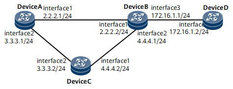
Networking Requirements
A RIP device periodically sends Update packets to a neighbor to detect neighbor reachability. By default, if a RIP device does not receive an Update packet from a neighbor within six Update periods (180s), the RIP device considers the neighbor Down. This means that RIP can detect a link fault only 180s after the link fails.
As technologies develop, voice, video, and other video on demand (VoD) services are widely applied. These services are sensitive to the packet loss and delay. Long-time fault detection will cause the loss of a large amount of data packets. As a result, the requirement of carrier-class networks for high reliability cannot be met. BFD for RIP can be deployed to address this problem. After BFD for RIP is configured, link fault detection can be completed within milliseconds, which speeds up RIP convergence.
On the network shown in Figure 1, Link Device A->Device B functions as the primary link and link Device A->Device C->Device B functions as the backup link. In most cases, service traffic is transmitted along the primary link. It is required that faults in the primary link be quickly detected and services be rapidly switched to the backup link. BFD for RIP can be configured. BFD is used to detect the RIP neighbor relationship between Device A and Device B. If the link between Device A and Device B fails, BFD can rapidly detect the failure and report it to RIP. This allows service traffic to be quickly switched to the backup link.
Configuration Roadmap
The configuration roadmap is as follows:
Configure basic RIP functions on each router to ensure that RIP neighbor relationships are established.
Enable BFD globally.
Configure BFD on interfaces at both ends of the link between Devices A and B.
Data Preparation
To complete the configuration, you need the following data:
Device A: RIP process ID (1), RIP version (2), IP address of GE 0/1/0 (2.2.2.1/24), and IP address of GE 0/1/8 (3.3.3.1/24)
Device B: RIP process ID (1), RIP version (2), IP address (2.2.2.2/24) of GE 0/1/0, IP address (4.4.4.1/24) of GE 0/1/8, and IP address (172.16.1.1/24) of GE 0/1/16
Device C: RIP process ID (1), RIP version (2), IP address (4.4.4.2/24) of GE 0/1/0, and IP address (3.3.3.2/24) of GE 0/1/8
Device D: RIP process ID (1), RIP version (2), and IP address (172.16.1.2/24) of GE 0/1/0
Devices A and B: minimum interval (100 ms) at which BFD packets are received or sent and local detection multiplier (10)
Procedure
- Configure an IP address for each interface.
In Figure 1, configure an IP address for each interface based on Data Preparation. For configuration details, see Configuration Files in this section.
- Configure basic RIP functions.
# Configure Device A.
<DeviceA> system-view
[~DeviceA] rip 1
[*DeviceA-rip-1] version 2
[*DeviceA-rip-1] network 2.0.0.0
[*DeviceA-rip-1] network 3.0.0.0
[*DeviceA-rip-1] commit
[~DeviceA-rip-1] quit
# Configure Device B.
<DeviceB> system-view
[~DeviceB] rip 1
[*DeviceB-rip-1] version 2
[*DeviceB-rip-1] network 2.0.0.0
[*DeviceB-rip-1] network 4.0.0.0
[*DeviceB-rip-1] network 172.16.0.0
[*DeviceB-rip-1] commit
[~DeviceB-rip-1] quit
# Configure Device C.
<DeviceC> system-view
[~DeviceC] rip 1
[*DeviceC-rip-1] version 2
[*DeviceC-rip-1] network 3.0.0.0
[*DeviceC-rip-1] network 4.0.0.0
[*DeviceC-rip-1] commit
[~DeviceC-rip-1] quit
# Configure Device D.
<DeviceD> system-view
[~DeviceD] rip 1
[*DeviceD-rip-1] version 2
[*DeviceD-rip-1] network 172.16.0.0
[*DeviceD-rip-1] commit
[~DeviceD-rip-1] quit
# After completing the preceding operations, run the display rip neighbor command. The command output shows that Devices A, B, and C have established neighbor relationships with each other. In the following example, the command output on Device A is used.
[~DeviceA] display rip 1 neighbor
---------------------------------------------------------------------
IP Address         Interface Type          Type       Last-Heard-Time
---------------------------------------------------------------------
 3.3.3.2         GigabitEthernet0/1/8        RIP    0:0:5
 Number of RIP routes  :2
 2.2.2.2         GigabitEthernet0/1/0        RIP    0:0:5
 Number of RIP routes  :4
# Run the display ip routing-table command. The command output shows that the routers have imported routes from each other. In the following example, the command output on Device A is used.
[~DeviceA] display ip routing-table
Route Flags: R - relay, D - download to fib, T - to vpn-instance, B - black hole route
------------------------------------------------------------------------------
Routing Table : _public_
         Destinations : 15       Routes : 15

Destination/Mask    Proto  Pre  Cost        Flags NextHop         Interface

        3.0.0.0/8   RIP    100  3             D  3.3.3.2         GigabitEthernet0/1/8
        3.3.3.0/24  Direct 0    0             D  3.3.3.1         GigabitEthernet0/1/8
        3.3.3.1/32  Direct 0    0             D  127.0.0.1       GigabitEthernet0/1/8
      3.3.3.255/32  Direct 0    0             D  127.0.0.1       GigabitEthernet0/1/8
        2.0.0.0/8   RIP    100  3             D  2.2.2.2         GigabitEthernet0/1/0
        2.2.2.0/24  Direct 0    0             D  2.2.2.1         GigabitEthernet0/1/0
        2.2.2.1/32  Direct 0    0             D  127.0.0.1       GigabitEthernet0/1/0
      2.2.2.255/32  Direct 0    0             D  127.0.0.1       GigabitEthernet0/1/0
      127.0.0.0/8   Direct 0    0             D  127.0.0.1       InLoopBack0
      127.0.0.1/32  Direct 0    0             D  127.0.0.1       InLoopBack0
127.255.255.255/32  Direct 0    0             D  127.0.0.1       InLoopBack0
     172.16.0.0/16  RIP    100  4             D  2.2.2.2         GigabitEthernet0/1/0
     172.16.1.0/24  RIP    100  1             D  2.2.2.2         GigabitEthernet0/1/0
        4.4.4.0/24  RIP    100  1             D  3.3.3.2         GigabitEthernet0/1/8
                    RIP    100  1             D  2.2.2.2         GigabitEthernet0/1/0
255.255.255.255/32  Direct 0    0             D  127.0.0.1       InLoopBack0
The preceding command output shows that the next-hop address and outbound interface of the route to 172.16.1.0/24 are 2.2.2.2 and GE 0/1/0, respectively and that traffic is transmitted over the primary link.
- Configure BFD in RIP processes.
# Configure BFD on all interfaces of Device A.
[~DeviceA] bfd
[*DeviceA-bfd] quit
[*DeviceA] rip 1
[*DeviceA-rip-1] bfd all-interfaces enable
[*DeviceA-rip-1] bfd all-interfaces min-rx-interval 100 min-tx-interval 100 detect-multiplier 10
[*DeviceA-rip-1] commit
[~DeviceA-rip-1] quit
The configuration on Device B is similar to that of Device A. For configuration details, see Configuration Files in this section.
# After completing the preceding operations, run the display rip bfd session command on router A. The command output shows that routers A and B have established a BFD session and the displayed BFDState field is Up. In the following example, the command output on Device A is used.
[~DeviceA] display rip 1 bfd session all
 Interface  :GigabitEthernet0/1/0
 LocalIp      :2.2.2.1         RemoteIp   :2.2.2.2        BFDState :Up

 Interface :GigabitEthernet0/2/0
 LocalIp      :3.3.3.1         RemoteIp  :3.3.3.2         BFDState :Down
- Verify the configuration.
# Run the shutdown command on GigabitEthernet0/1/0 of Device B to simulate a fault in the primary link.

The link fault is simulated to verify the configuration. The operation is not required on the live network.
[~DeviceB] interface gigabitethernet0/1/0
[~DeviceB-GigabitEthernet0/1/0] shutdown
[*DeviceB-GigabitEthernet0/1/0] commit
# Check information about the BFD session on Device A. The command output shows that there is no BFD session between Devices A and B.
[~DeviceA] display rip 1 bfd session all
 LocalIp       :3.3.3.1         RemoteIp  :3.3.3.2         BFDState  :Down
 TX            :0               RX        :0               Multiplier:0
 BFD Local Dis :8200            Interface :GigabitEthernet0/1/8
 Diagnostic Info:No diagnostic information
# Check the routing table of Device A.
[~DeviceA] display ip routing-table
Route Flags: R - relay, D - download to fib, T - to vpn-instance, B - black hole route
------------------------------------------------------------------------------
Routing Table : _public_
         Destinations : 8        Routes : 8

Destination/Mask    Proto  Pre  Cost        Flags NextHop         Interface

        3.3.3.0/24  Direct 0    0             D  3.3.3.1         GigabitEthernet0/1/8
        3.3.3.1/32  Direct 0    0             D  127.0.0.1       GigabitEthernet0/1/8
      3.3.3.255/32  Direct 0    0             D  127.0.0.1       GigabitEthernet0/1/8
      127.0.0.0/8   Direct 0    0             D  127.0.0.1       InLoopBack0
      127.0.0.1/32  Direct 0    0             D  127.0.0.1       InLoopBack0
127.255.255.255/32  Direct 0    0             D  127.0.0.1       InLoopBack0
     172.16.1.0/24  RIP    100  2             D  3.3.3.2         GigabitEthernet0/1/8
255.255.255.255/32  Direct 0    0             D  127.0.0.1       InLoopBack0
The preceding command output shows that the backup link Device A->Device C->Device B is used and that the next hop address and outbound interface of the route to 172.16.0.0/16 are 3.3.3.2 and GigabitEthernet0/1/8, respectively.
Configuration Files
Device A configuration file
#
 sysname DeviceA
#
bfd
#
interface gigabitethernet0/1/0
 undo shutdown
 ip address 2.2.2.1 255.255.255.0
#
interface gigabitethernet0/1/8
 undo shutdown
 ip address 3.3.3.1 255.255.255.0
#
rip 1
 version 2
 network 2.0.0.0
 network 3.0.0.0
 bfd all-interfaces enable
 bfd all-interfaces min-tx-interval 100 min-rx-interval 100 detect-multiplier 10
#
return
Device B configuration file
#
 sysname DeviceB
#
bfd
#
interface gigabitethernet0/1/0
 undo shutdown
 ip address 2.2.2.2 255.255.255.0
#
interface gigabitethernet0/1/8
 undo shutdown
 ip address 4.4.4.1 255.255.255.0
#
interface gigabitethernet0/1/16
 undo shutdown
 ip address 172.16.1.1 255.255.255.0
rip 1
 version 2
 network 2.0.0.0
 network 4.0.0.0
 network 172.16.0.0
 bfd all-interfaces enable
 bfd all-interfaces min-tx-interval 100 min-rx-interval 100 detect-multiplier 10
#
return
Device C configuration file
#
 sysname DeviceC
#
interface gigabitethernet0/1/0
 undo shutdown
 ip address 4.4.4.2 255.255.255.0
#
interface gigabitethernet0/1/8
 undo shutdown
 ip address 3.3.3.2 255.255.255.0
#
rip 1
 version 2
 network 3.0.0.0
 network 4.0.0.0
#
return
Device D configuration file
#
 sysname DeviceD
#
interface gigabitethernet0/1/0
 undo shutdown
 ip address 172.16.1.2 255.255.255.0
#
rip 1
 version 2
 network 172.16.0.0
#
return