Example for Configuring Static BFD for RIP
This section provides an example for configuring static BFD for RIP.
Networking Requirements
RIP detects neighbor status by exchanging Update packets periodically. By default, if a local device does not receive any Update packets from its neighbor within six update intervals (180s), the local device considers the neighbor Down.
As technologies develop, voice, video, and other video on demand (VoD) services are widely applied. These services are sensitive to the packet loss and delay. Long-time fault detection will cause the loss of a large amount of data packets. As a result, the requirement of carrier-class networks for high reliability cannot be met. BFD for RIP can be deployed to address this problem. After BFD for RIP is configured, link fault detection can be completed within milliseconds, which speeds up RIP convergence.
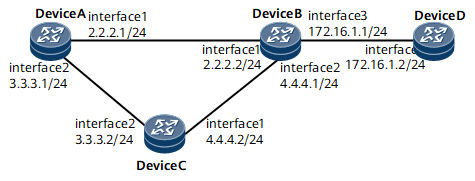
Use Figure 1 as an example.
- RIP runs between DeviceA, Device B, Device C, and Device D.
- Service traffic travels through the primary link Device A → Device B → Device D. Static BFD is enabled on interfaces connecting Device A and Device B. If the primary link fails, BFD can rapidly detect the fault and notify the RIP module of the fault. Service traffic is then switched to a backup link.
Configuration Roadmap
The configuration roadmap is as follows:
Configure basic RIP functions on each router to set up RIP neighbor relationships.
Enable global BFD.
Enable static BFD on interfaces connecting Device A and Device B.
Data Preparation
To complete the configuration, you need the following data:
On Device A: RIP process ID (1), RIP version number (2), IP address of GE 0/1/0 (2.2.2.1/24), and IP address of GE 0/1/8 (3.3.3.1/24)
On Device B: RIP process ID (1), RIP version number (2), IP address of GE 0/1/0 (2.2.2.2/24), IP address of GE 0/1/8 (4.4.4.1/24), IP address of GE 0/1/16 (172.16.1.1/24)
On Device C: RIP process ID (1), RIP version number (2), IP address of GE 0/1/0 (4.4.4.2/24), and IP address of GE 0/1/8 (3.3.3.2/24)
On Device D: RIP process ID (1), RIP version number (2), and IP address of GE 0/1/0 (172.16.1.2/24)
Local and the remote discriminators used for BFD sessions between Device A and Device B
Procedure
- Configure an IP address for each interface.
Configure IP addresses based on Figure 1 and Data Preparation. For details about the configuration, see Configuration files in this section.
- Configure basic RIP functions.
# Configure Device A.
<DeviceA> system-view
[~DeviceA] rip 1
[*DeviceA-rip-1] version 2
[*DeviceA-rip-1] network 2.0.0.0
[*DeviceA-rip-1] network 3.0.0.0
[*DeviceA-rip-1] commit
[~DeviceA-rip-1] quit
# Configure Device B.
<DeviceB> system-view
[~DeviceB] rip 1
[*DeviceB-rip-1] version 2
[*DeviceB-rip-1] network 2.0.0.0
[*DeviceB-rip-1] network 4.0.0.0
[*DeviceB-rip-1] network 172.16.0.0
[*DeviceB-rip-1] commit
[~DeviceB-rip-1] quit
# Configure Device C.
<DeviceC> system-view
[~DeviceC] rip 1
[*DeviceC-rip-1] version 2
[*DeviceC-rip-1] network 3.0.0.0
[*DeviceC-rip-1] network 4.0.0.0
[*DeviceC-rip-1] commit
[~DeviceC-rip-1] quit
# Configure Device D.
<DeviceD> system-view
[~DeviceD] rip 1
[*DeviceD-rip-1] version 2
[*DeviceD-rip-1] network 172.16.0.0
[*DeviceD-rip-1] commit
[~DeviceD-rip-1] quit
# After the configurations are complete, run the display rip neighbor command to check whether RIP neighbor relationships among Device A, Device B, and Device C are established. The following command output uses Device A as an example.
[~DeviceA] display rip 1 neighbor
---------------------------------------------------------------------
 IP Address      Interface                   Type   Last-Heard-Time
---------------------------------------------------------------------
 3.3.3.2         GigabitEthernet0/1/8        RIP    0:0:5
 Number of RIP routes  :2
 2.2.2.2         GigabitEthernet0/1/0        RIP    0:0:5
 Number of RIP routes  :4
# Run the display ip routing-table command to check whether routers have learned routes from each other. The following command output uses Device A as an example.
[~DeviceA] display ip routing-table
Route Flags: R - relay, D - download to fib, T - to vpn-instance, B - black hole route
------------------------------------------------------------------------------
Routing Table : _public_
         Destinations : 15       Routes : 15

Destination/Mask    Proto  Pre  Cost        Flags NextHop         Interface

        3.0.0.0/8   RIP    100  3             D  3.3.3.2         GigabitEthernet0/1/8
        3.3.3.0/24  Direct 0    0             D  3.3.3.1         GigabitEthernet0/1/8
        3.3.3.1/32  Direct 0    0             D  127.0.0.1       GigabitEthernet0/1/8
      3.3.3.255/32  Direct 0    0             D  127.0.0.1       GigabitEthernet0/1/8
        2.0.0.0/8   RIP    100  3             D  2.2.2.2         GigabitEthernet0/1/0
        2.2.2.0/24  Direct 0    0             D  2.2.2.1         GigabitEthernet0/1/0
        2.2.2.1/32  Direct 0    0             D  127.0.0.1       GigabitEthernet0/1/0
      2.2.2.255/32  Direct 0    0             D  127.0.0.1       GigabitEthernet0/1/0
      127.0.0.0/8   Direct 0    0             D  127.0.0.1       InLoopBack0
      127.0.0.1/32  Direct 0    0             D  127.0.0.1       InLoopBack0
127.255.255.255/32  Direct 0    0             D  127.0.0.1       InLoopBack0
     172.16.0.0/16  RIP    100  4             D  2.2.2.2         GigabitEthernet0/1/0
     172.16.1.0/24  RIP    100  1             D  2.2.2.2         GigabitEthernet0/1/0
        4.4.4.0/24  RIP    100  1             D  3.3.3.2         GigabitEthernet0/1/8
                    RIP    100  1             D  2.2.2.2         GigabitEthernet0/1/0
255.255.255.255/32  Direct 0    0             D  127.0.0.1       InLoopBack0
The routing table shows that the next hop IP address of the route destined for 172.16.0.0/16 is 2.2.2.2, the outbound interface is GigabitEthernet 0/1/0, and that traffic is transmitted along the primary link.
- Configure static BFD on Device A.
# Configure BFD on Device A.
[~DeviceA] bfd
[*DeviceA-bfd] quit
[*DeviceA] bfd 1 bind peer-ip 2.2.2.2 interface gigabitethernet 0/1/0 source-ip 2.2.2.1
[*DeviceA-bfd-session-1] discriminator local 1
[*DeviceA-bfd-session-1] discriminator remote 2
[*DeviceA-bfd-session-1] commit
[~DeviceA-bfd-session-1] quit
[~DeviceA] interface gigabitethernet0/1/0
[~HUAWEIA-GigabitEthernet0/1/0] rip bfd static
# Configure BFD on Device B.
[~DeviceB] bfd
[*DeviceB-bfd] quit
[*DeviceB] bfd 1 bind peer-ip 2.2.2.1 interface gigabitethernet 0/1/0 source-ip 2.2.2.2
[*DeviceB-bfd-session-1] discriminator local 2
[*DeviceB-bfd-session-1] discriminator remote 1
[*DeviceB-bfd-session-1] commit
[~DeviceB-bfd-session-1] quit
[~DeviceB] interface gigabitethernet0/1/0
[~HUAWEIB-GigabitEthernet0/1/0] rip bfd static
# After the configurations are complete, run the display bfd session all command on Device A to check whether a static BFD session has been set up.
[~DeviceA] display bfd session all
(w): State in WTR
(*): State is invalid
------------------------------------------------------------------------------
Local  Remote  PeerIpAddr      State     Type        InterfaceName
------------------------------------------------------------------------------
1      2       2.2.2.2         Up        S_IP_IF     GigabitEthernet0/1/0
------------------------------------------------------------------------------
    Total UP/DOWN Session Number : 1/0
- Verify the configuration.
# Run the shutdown command on GigabitEthernet 0/1/0 on Device B to simulate a fault on the primary link.

The link fault is simulated to verify the configuration. The operation is not required on the live network.
[~DeviceB] interface gigabitethernet0/1/0
[~DeviceB-GigabitEthernet0/1/0] shutdown
[*DeviceB-GigabitEthernet0/1/0] commit
# Check the BFD session information of Device A. The command output that there is no BFD session between Device A and Device B.
# Check the routing table of Device A.
[~DeviceA] display ip routing-table
Route Flags: R - relay, D - download to fib, T - to vpn-instance, B - black hole route
------------------------------------------------------------------------------
Routing Table : _public_
         Destinations : 8        Routes : 8

Destination/Mask    Proto  Pre  Cost        Flags NextHop         Interface

        3.3.3.0/24  Direct 0    0             D  3.3.3.1         GigabitEthernet0/1/8
        3.3.3.1/32  Direct 0    0             D  127.0.0.1       GigabitEthernet0/1/8
      3.3.3.255/32  Direct 0    0             D  127.0.0.1       GigabitEthernet0/1/8
      127.0.0.0/8   Direct 0    0             D  127.0.0.1       InLoopBack0
      127.0.0.1/32  Direct 0    0             D  127.0.0.1       InLoopBack0
127.255.255.255/32  Direct 0    0             D  127.0.0.1       InLoopBack0
     172.16.1.0/24  RIP    100  2             D  3.3.3.2         GigabitEthernet0/1/8
255.255.255.255/32  Direct 0    0             D  127.0.0.1       InLoopBack0
The routing table shows that the backup link takes over traffic. The next hop IP address of the route destined for 172.16.0.0/16 is 3.3.3.2, and that the outbound interface is GigabitEthernet 0/1/8.
Configuration files
Device A configuration file
#
 sysname DeviceA
#
bfd
#
interface gigabitethernet0/1/0
 undo shutdown
 ip address 2.2.2.1 255.255.255.0
 rip bfd static
#
interface gigabitethernet0/1/8
 undo shutdown
 ip address 3.3.3.1 255.255.255.0
#
rip 1
 version 2
 network 2.0.0.0
 network 3.0.0.0
#
bfd 1 bind peer-ip 2.2.2.2 interface gigabitethernet0/1/0 source-ip 2.2.2.1
 discriminator local 1
 discriminator remote 2
#
return
Device B configuration file
#
 sysname DeviceB
#
bfd
#
interface gigabitethernet0/1/0
 undo shutdown
 ip address 2.2.2.2 255.255.255.0
 rip bfd static
#
interface gigabitethernet0/1/8
 undo shutdown
 ip address 4.4.4.1 255.255.255.0
#
interface gigabitethernet0/1/16
 undo shutdown
 ip address 172.16.1.1 255.255.255.0
#
rip 1
 version 2
 network 2.0.0.0
 network 4.0.0.0
 network 172.16.0.0
#
bfd 1 bind peer-ip 2.2.2.1 interface gigabitethernet0/1/0 source-ip 2.2.2.2
 discriminator local 2
 discriminator remote 1
#
return
Device C configuration file
#
 sysname DeviceC
#
interface gigabitethernet0/1/0
 undo shutdown
 ip address 4.4.4.2 255.255.255.0
#
interface gigabitethernet0/1/8
 undo shutdown
 ip address 3.3.3.2 255.255.255.0
#
rip 1
 version 2
 network 3.0.0.0
 network 4.0.0.0
#
return
Device D configuration file
#
 sysname DeviceD
#
interface gigabitethernet0/1/0
 undo shutdown
 ip address 172.16.1.2 255.255.255.0
#
rip 1
 version 2
 network 172.16.0.0
#
return