Example for Configuring CBTS in an L3VPN over SR-MPLS TE Scenario
This section provides an example for configuring class-of-service-based tunnel selection (CBTS) in an L3VPN over SR-MPLS TE scenario.
Networking Requirements
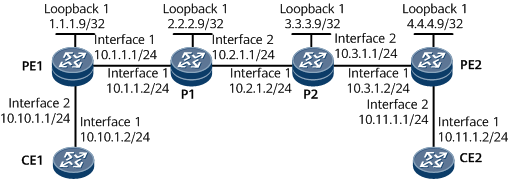
On the network shown in Figure 1, CE1 and CE2 belong to the same L3VPN. They access the public network through PE1 and PE2, respectively. Various types of services are transmitted between CE1 and CE2. Transmitting a large number of common services deteriorates the efficiency of transmitting important services. To prevent this problem, configure the CBTS function. This function allows traffic of a specific service class to be transmitted along a specified tunnel.
In this example, Tunnel1 and Tunnel2 on PE1 transmit important services, and Tunnel3 transmits other services.

If the CBTS function is configured, you are advised not to configure any of the following functions:
- Mixed load balancing
- Dynamic load balancing
Configuration Roadmap
The configuration roadmap is as follows:
Assign an IP address and its mask to each interface and configure a loopback interface address as an LSR ID on each node.
Enable IS-IS globally, configure network entity titles (NETs), specify the cost type, and enable IS-IS TE. Enable IS-IS on interfaces, including loopback interfaces.
Set MPLS LSR IDs and enable MPLS and MPLS TE globally.
Enable MPLS and MPLS TE on each interface.
Configure the maximum reservable link bandwidth and BC for the outbound interface of each involved tunnel.
Create a tunnel interface on the ingress and configure the IP address, tunnel protocol, destination IP address, and tunnel bandwidth.
Configure multi-field classification on PE1.
Configure a VPN instance and apply a tunnel policy on PE1.
Data Preparation
To complete the configuration, you need the following data:
IS-IS area ID, originating system ID, and IS-IS level on each node
Maximum reservable link bandwidth of each tunnel
Tunnel interface number, IP address, destination IP address, tunnel ID, and tunnel bandwidth
Traffic classifier name, traffic behavior name, and traffic policy name
Procedure
- Assign an IP address and its mask to each interface.
# Configure PE1.
<HUAWEI> system-view
[~HUAWEI] sysname PE1
[*HUAWEI] commit
[~PE1] interface loopback 1
[*PE1-LoopBack1] ip address 1.1.1.9 32
[*PE1-LoopBack1] quit
[*PE1] interface gigabitethernet0/1/0
[*PE1-GigabitEthernet0/1/0] ip address 10.1.1.1 24
[*PE1-GigabitEthernet0/1/0] quit
[*PE1] commit
# Configure P1.
<HUAWEI> system-view
[~HUAWEI] sysname P1
[*HUAWEI] commit
[~P1] interface loopback 1
[*P1-LoopBack1] ip address 2.2.2.9 32
[*P1-LoopBack1] quit
[*P1] interface gigabitethernet0/1/0
[*P1-GigabitEthernet0/1/0] ip address 10.1.1.2 24
[*P1-GigabitEthernet0/1/0] quit
[*P1] interface gigabitethernet0/1/8
[*P1-GigabitEthernet0/1/8] ip address 10.2.1.1 24
[*P1-GigabitEthernet0/1/8] quit
[*P1] commit
# Configure P2.
<HUAWEI> system-view
[~HUAWEI] sysname P2
[*HUAWEI] commit
[~P2] interface loopback 1
[*P2-LoopBack1] ip address 3.3.3.9 32
[*P2-LoopBack1] quit
[*P2] interface gigabitethernet0/1/0
[*P2-GigabitEthernet0/1/0] ip address 10.2.1.2 24
[*P2-GigabitEthernet0/1/0] quit
[*P2] interface gigabitethernet0/1/8
[*P2-GigabitEthernet0/1/8] ip address 10.3.1.1 24
[*P2-GigabitEthernet0/1/8] quit
[*P2] commit
# Configure PE2.
<HUAWEI> system-view
[~HUAWEI] sysname PE2
[*HUAWEI] commit
[~PE2] interface loopback 1
[*PE2-LoopBack1] ip address 4.4.4.9 32
[*PE2-LoopBack1] quit
[*PE2] interface gigabitethernet0/1/0
[*PE2-GigabitEthernet0/1/0] ip address 10.3.1.2 24
[*PE2-GigabitEthernet0/1/0] quit
[*PE2] commit
- Configure IS-IS to advertise routes.
# Configure PE1.
[~PE1] isis 1
[*PE1-isis-1] network-entity 00.0005.0000.0000.0001.00
[*PE1-isis-1] is-level level-2
[*PE1-isis-1] quit
[*PE1] interface gigabitethernet 0/1/0
[*PE1-GigabitEthernet0/1/0] isis enable 1
[*PE1-GigabitEthernet0/1/0] quit
[*PE1] interface loopback 1
[*PE1-LoopBack1] isis enable 1
[*PE1-LoopBack1] commit
[~PE1-LoopBack1] quit
# Configure P1.
[~P1] isis 1
[*P1-isis-1] network-entity 00.0005.0000.0000.0002.00
[*P1-isis-1] is-level level-2
[*P1-isis-1] quit
[*P1] interface gigabitethernet 0/1/0
[*P1-GigabitEthernet0/1/0] isis enable 1
[*P1-GigabitEthernet0/1/0] quit
[*P1] interface gigabitethernet 0/1/8
[*P1-GigabitEthernet0/1/8] isis enable 1
[*P1-GigabitEthernet0/1/8] quit
[*P1] interface loopback 1
[*P1-LoopBack1] isis enable 1
[*P1-LoopBack1] commit
[~P1-LoopBack1] quit
# Configure P2.
[~P2] isis 1
[*P2-isis-1] network-entity 00.0005.0000.0000.0003.00
[*P2-isis-1] is-level level-2
[*P2-isis-1] quit
[*P2] interface gigabitethernet 0/1/0
[*P2-GigabitEthernet0/1/0] isis enable 1
[*P2-GigabitEthernet0/1/0] quit
[*P2] interface gigabitethernet 0/1/8
[*P2-GigabitEthernet0/1/8] isis enable 1
[*P2-GigabitEthernet0/1/8] quit
[*P2] interface loopback 1
[*P2-LoopBack1] isis enable 1
[*P2-LoopBack1] commit
[~P2-LoopBack1] quit
# Configure PE2.
[~PE2] isis 1
[*PE2-isis-1] network-entity 00.0005.0000.0000.0004.00
[*PE2-isis-1] is-level level-2
[*PE2-isis-1] quit
[*PE2] interface gigabitethernet 0/1/0
[*PE2-GigabitEthernet0/1/0] isis enable 1
[*PE2-GigabitEthernet0/1/0] quit
[*PE2] interface loopback 1
[*PE2-LoopBack1] isis enable 1
[*PE2-LoopBack1] commit
[~PE2-LoopBack1] quit
After completing the preceding configurations, run the display ip routing-table command on each node to check that both PEs have learned routes from each other. The following example uses the command output on PE1.
[~PE1] display ip routing-table
Route Flags: R - relay, D - download to fib, T - to vpn-instance, B - black hole route
------------------------------------------------------------------------------
Routing Table : _public_
         Destinations : 13       Routes : 13

Destination/Mask    Proto     Pre  Cost        Flags NextHop         Interface

        1.1.1.9/32  Direct    0    0             D  127.0.0.1       LoopBack1
        2.2.2.9/32  ISIS-L2   15   10            D  10.1.1.2        GigabitEthernet0/1/0
        3.3.3.9/32  ISIS-L2   15   20            D  10.1.1.2        GigabitEthernet0/1/0
        4.4.4.9/32  ISIS-L2   15   30            D  10.1.1.2        GigabitEthernet0/1/0
       10.1.1.0/24  Direct    0    0             D  10.1.1.1        GigabitEthernet0/1/0
       10.1.1.1/32  Direct    0    0             D  127.0.0.1       GigabitEthernet0/1/0
     10.1.1.255/32  Direct    0    0             D  127.0.0.1       GigabitEthernet0/1/0
       10.2.1.0/24  ISIS-L2   15   20            D  10.1.1.2        GigabitEthernet0/1/0
       10.3.1.0/24  ISIS-L2   15   30            D  10.1.1.2        GigabitEthernet0/1/0
      127.0.0.0/8   Direct    0    0             D  127.0.0.1       InLoopBack0
      127.0.0.1/32  Direct    0    0             D  127.0.0.1       InLoopBack0
127.255.255.255/32  Direct    0    0             D  127.0.0.1       InLoopBack0
255.255.255.255/32  Direct    0    0             D  127.0.0.1       InLoopBack0
- Establish an MP-IBGP peer relationship between PEs.
# Configure PE1.
[~PE1] bgp 100
[*PE1-bgp] peer 4.4.4.9 as-number 100
[*PE1-bgp] peer 4.4.4.9 connect-interface loopback 1
[*PE1-bgp] ipv4-family vpnv4
[*PE1-bgp-af-vpnv4] peer 4.4.4.9 enable
[*PE1-bgp-af-vpnv4] commit
[~PE1-bgp-af-vpnv4] quit
[~PE1-bgp] quit
# Configure PE2.
[~PE2] bgp 100
[*PE2-bgp] peer 1.1.1.9 as-number 100
[*PE2-bgp] peer 1.1.1.9 connect-interface loopback 1
[*PE2-bgp] ipv4-family vpnv4
[*PE2-bgp-af-vpnv4] peer 1.1.1.9 enable
[*PE2-bgp-af-vpnv4] commit
[~PE2-bgp-af-vpnv4] quit
[~PE2-bgp] quit
After the configuration is complete, run the display bgp peer or display bgp vpnv4 all peer command on the PEs to check whether a BGP peer relationship has been established between the PEs. If the Established state is displayed in the command output, the BGP peer relationship has been established successfully. The following example uses the command output on PE1.
[~PE1] display bgp peer
 BGP local router ID : 1.1.1.9
 Local AS number : 100
 Total number of peers : 1          Peers in established state : 1
  Peer            V    AS  MsgRcvd  MsgSent     OutQ  Up/Down    State        PrefRcv
  4.4.4.9         4   100        2        6     0     00:11:25   Established   0
[~PE1] display bgp vpnv4 all peer
 BGP local router ID : 1.1.1.9
 Local AS number : 100
 Total number of peers : 1                 Peers in established state : 1
  Peer            V    AS  MsgRcvd  MsgSent    OutQ  Up/Down    State        PrefRcv
  4.4.4.9         4   100   19      21         0     00:19:43   Established   0
- Configure basic MPLS functions and enable MPLS TE.
# Enable MPLS and MPLS TE both globally and on specific interfaces for nodes along each tunnel.
# Configure PE1.
[~PE1] mpls lsr-id 1.1.1.9
[*PE1] mpls
[*PE1-mpls] mpls te
[*PE1-mpls] quit
[*PE1] interface gigabitethernet 0/1/0
[*PE1-GigabitEthernet0/1/0] mpls
[*PE1-GigabitEthernet0/1/0] mpls te
[*PE1-GigabitEthernet0/1/0] commit
[~PE1-GigabitEthernet0/1/0] quit
# Configure P1.
[~P1] mpls lsr-id 2.2.2.9
[*P1] mpls
[*P1-mpls] mpls te
[*P1-mpls] quit
[*P1] interface gigabitethernet 0/1/0
[*P1-GigabitEthernet0/1/0] mpls
[*P1-GigabitEthernet0/1/0] mpls te
[*P1-GigabitEthernet0/1/0] quit
[*P1] interface gigabitethernet 0/1/8
[*P1-GigabitEthernet0/1/8] mpls
[*P1-GigabitEthernet0/1/8] mpls te
[*P1-GigabitEthernet0/1/8] commit
[~P1-GigabitEthernet0/1/8] quit
# Configure P2.
[~P2] mpls lsr-id 3.3.3.9
[*P2] mpls
[*P2-mpls] mpls te
[*P2-mpls] quit
[*P2] interface gigabitethernet 0/1/0
[*P2-GigabitEthernet0/1/0] mpls
[*P2-GigabitEthernet0/1/0] mpls te
[*P2-GigabitEthernet0/1/0] quit
[*P2] interface gigabitethernet 0/1/8
[*P2-GigabitEthernet0/1/8] mpls
[*P2-GigabitEthernet0/1/8] mpls te
[*P2-GigabitEthernet0/1/0] commit
[~P2-GigabitEthernet2/0/0] quit
# Configure PE2.
[~PE2] mpls lsr-id 4.4.4.9
[*PE2] mpls
[*PE2-mpls] mpls te
[*PE2-mpls] quit
[*PE2] interface gigabitethernet 0/1/0
[*PE2-GigabitEthernet0/1/0] mpls
[*PE2-GigabitEthernet0/1/0] mpls te
[*PE2-GigabitEthernet0/1/0] commit
[~PE2-GigabitEthernet0/1/0] quit
- Configure MPLS TE bandwidth attributes for links.
# Configure the maximum reservable link bandwidth and BC0 for the outbound interfaces of each tunnel.
# Configure PE1.
[~PE1] interface gigabitethernet 0/1/0
[~PE1-GigabitEthernet0/1/0] mpls te bandwidth max-reservable-bandwidth 100000
[*PE1-GigabitEthernet0/1/0] mpls te bandwidth bc0 100000
[*PE1-GigabitEthernet0/1/0] commit
[~PE1-GigabitEthernet0/1/0] quit
# Configure P1.
[~P1] interface gigabitethernet 0/1/0
[~P1-GigabitEthernet0/1/0] mpls te bandwidth max-reservable-bandwidth 100000
[*P1-GigabitEthernet0/1/0] mpls te bandwidth bc0 100000
[*P1-GigabitEthernet0/1/0] quit
[*P1] interface gigabitethernet 0/1/8
[*P1-GigabitEthernet0/1/8] mpls te bandwidth max-reservable-bandwidth 100000
[*P1-GigabitEthernet0/1/8] mpls te bandwidth bc0 100000
[*P1-GigabitEthernet0/1/8] commit
[~P1-GigabitEthernet0/1/8] quit
# Configure P2.
[~P2] interface gigabitethernet 0/1/0
[~P2-GigabitEthernet0/1/0] mpls te bandwidth max-reservable-bandwidth 100000
[*P2-GigabitEthernet0/1/0] mpls te bandwidth bc0 100000
[*P2-GigabitEthernet0/1/0] quit
[*P2] interface gigabitethernet 0/1/8
[*P2-GigabitEthernet0/1/8] mpls te bandwidth max-reservable-bandwidth 100000
[*P2-GigabitEthernet0/1/8] mpls te bandwidth bc0 100000
[*P2-GigabitEthernet0/1/8] commit
[~P2-GigabitEthernet0/1/8] quit
# Configure PE2.
[~PE2] interface gigabitethernet 0/1/0
[~PE2-GigabitEthernet0/1/0] mpls te bandwidth max-reservable-bandwidth 100000
[*PE2-GigabitEthernet0/1/0] mpls te bandwidth bc0 100000
[*PE2-GigabitEthernet0/1/0] commit
[~PE2-GigabitEthernet0/1/0] quit
- Configure QoS on each PE.
# Configure multi-field classification and set a service class for each type of service packet on PE1.
[~PE1] acl 2001
[*PE1-acl4-basic-2001] rule 10 permit source 10.40.0.0 0.0.255.255
[*PE1-acl4-basic-2001] quit
[*PE1] acl 2002
[*PE1-acl4-basic-2002] rule 20 permit source 10.50.0.0 0.0.255.255
[*PE1-acl4-basic-2002] quit
[*PE1] traffic classifier service1
[*PE1-classifier-service1] if-match acl 2001
[*PE1-classifier-service1] commit
[~PE1-classifier-service1] quit
[~PE1] traffic behavior behavior1
[*PE1-behavior-behavior1] service-class af1 color green
[*PE1-behavior-behavior1] commit
[~PE1-behavior-behavior1] quit
[~PE1] traffic classifier service2
[*PE1-classifier-service2] if-match acl 2002
[*PE1-classifier-service2] commit
[~PE1-classifier-service2] quit
[~PE1] traffic behavior behavior2
[*PE1-behavior-behavior2] service-class af2 color green
[*PE1-behavior-behavior2] commit
[~PE1-behavior-behavior2] quit
[~PE1] traffic policy policy1
[*PE1-trafficpolicy-policy1] classifier service1 behavior behavior1
[*PE1-trafficpolicy-policy1] classifier service2 behavior behavior2
[*PE1-trafficpolicy-policy1] commit
[~PE1-trafficpolicy-policy1] quit
[~PE1] interface gigabitethernet 0/1/8
[~PE1-GigabitEthernet0/1/8] traffic-policy policy1 inbound
[*PE1-GigabitEthernet0/1/8] commit
[~PE1-GigabitEthernet0/1/8] quit
- Enable SR and configure an explicit path.
In this example, the explicit path is used to establish an SR-MPLS TE tunnel.

The SRGB range varies according to the device. The range specified in this example is for reference only.
# Configure PE1.
[~PE1] segment-routing
[*PE1-segment-routing] quit
[*PE1] isis 1
[*PE1-isis-1] cost-style wide
[*PE1-isis-1] traffic-eng level-2
[*PE1-isis-1] segment-routing mpls
[*PE1-isis-1] segment-routing global-block 16000 19000
[*PE1-isis-1] commit
[~PE1-isis-1] quit
[~PE1] interface LoopBack 1
[~PE1-LoopBack1] isis prefix-sid index 10
[*PE1-LoopBack1] commit
[~PE1-LoopBack1] quit
# Configure P1.
[~P1] segment-routing
[*P1-segment-routing] quit
[*P1] isis 1
[*P1-isis-1] cost-style wide
[*P1-isis-1] traffic-eng level-2
[*P1-isis-1] segment-routing mpls
[*P1-isis-1] segment-routing global-block 16000 19000
[*P1-isis-1] commit
[~P1-isis-1] quit
[~P1] interface LoopBack 1
[~P1-LoopBack1] isis prefix-sid index 20
[*P1-LoopBack1] commit
[~P1-LoopBack1] quit
# Configure P2.
[~P2] segment-routing
[*P2-segment-routing] quit
[*P2] isis 1
[*P2-isis-1] cost-style wide
[*P2-isis-1] traffic-eng level-2
[*P2-isis-1] segment-routing mpls
[*P2-isis-1] segment-routing global-block 16000 19000
[*P2-isis-1] commit
[~P2-isis-1] quit
[~P2] interface LoopBack 1
[~P2-LoopBack1] isis prefix-sid index 30
[*P2-LoopBack1] commit
[~P2-LoopBack1] quit
# Configure PE2.
[~PE2] segment-routing
[*PE2-segment-routing] quit
[*PE2] isis 1
[*PE2-isis-1] cost-style wide
[*PE2-isis-1] traffic-eng level-2
[*PE2-isis-1] segment-routing mpls
[*PE2-isis-1] segment-routing global-block 16000 19000
[*PE2-isis-1] commit
[~PE2-isis-1] quit
[~PE2] interface LoopBack 1
[~PE2-LoopBack1] isis prefix-sid index 40
[*PE2-LoopBack1] commit
[~PE2-LoopBack1] quit
# Display the node SID of each node. The following example uses the command output on PE1.
[~PE1] display segment-routing prefix mpls forwarding

                   Segment Routing Prefix MPLS Forwarding Information
             --------------------------------------------------------------
             Role : I-Ingress, T-Transit, E-Egress, I&T-Ingress And Transit

Prefix             Label      OutLabel   Interface         NextHop          Role  MPLSMtu   Mtu     State
-----------------------------------------------------------------------------------------------------------------
1.1.1.9/32         16010      NULL       Loop1             127.0.0.1        E     ---       1500    Active
2.2.2.9/32         16020      3          GE0/1/0           10.1.1.2         I&T   ---       1500    Active
3.3.3.9/32         16030      16030      GE0/1/0           10.1.1.2         I&T   ---       1500    Active
4.4.4.9/32         16040      16040      GE0/1/0           10.1.1.2         I&T   ---       1500    Active

Total information(s): 4
# Configure an explicit path from PE1 to PE2.
[~PE1] explicit-path pe1_pe2
[*PE1-explicit-path-pe1_pe2] next sid label 16020 type prefix
[*PE1-explicit-path-pe1_pe2] next sid label 16030 type prefix
[*PE1-explicit-path-pe1_pe2] next sid label 16040 type prefix
[*PE1-explicit-path-pe1_pe2] commit
[~PE1-explicit-path-pe1_pe2] quit
# Configure an explicit path from PE2 to PE1.
[~PE2] explicit-path pe2_pe1
[*PE2-explicit-path-pe2_pe1] next sid label 16030 type prefix
[*PE2-explicit-path-pe2_pe1] next sid label 16020 type prefix
[*PE2-explicit-path-pe2_pe1] next sid label 16010 type prefix
[*PE2-explicit-path-pe2_pe1] commit
[~PE2-explicit-path-pe2_pe1] quit
- Configure MPLS TE tunnel interfaces.
# On the ingress of each tunnel, create a tunnel interface and set the IP address, tunnel protocol, destination IP address, tunnel ID, dynamic signaling protocol, tunnel bandwidth, and service classes for packets transmitted on the tunnel.
Run the mpls te service-class { service-class & <1-8> | default } command to set a service class for packets carried by each tunnel.
# Configure PE1.
[~PE1] interface Tunnel1
[*PE1-Tunnel1] ip address unnumbered interface loopback 1
[*PE1-Tunnel1] tunnel-protocol mpls te
[*PE1-Tunnel1] destination 4.4.4.9
[*PE1-Tunnel1] mpls te tunnel-id 1
[*PE1-Tunnel1] mpls te bandwidth ct0 20000
[*PE1-Tunnel1] mpls te signal-protocol segment-routing
[*PE1-Tunnel1] mpls te path explicit-path pe1_pe2
[*PE1-Tunnel1] mpls te service-class af1
[*PE1-Tunnel1] commit
[~PE1-Tunnel1] quit
[~PE1] interface Tunnel2
[*PE1-Tunnel2] ip address unnumbered interface loopback 1
[*PE1-Tunnel2] tunnel-protocol mpls te
[*PE1-Tunnel2] destination 4.4.4.9
[*PE1-Tunnel2] mpls te tunnel-id 2
[*PE1-Tunnel2] mpls te bandwidth ct0 20000
[*PE1-Tunnel2] mpls te signal-protocol segment-routing
[*PE1-Tunnel2] mpls te path explicit-path pe1_pe2
[*PE1-Tunnel2] mpls te service-class af2
[*PE1-Tunnel2] commit
[~PE1-Tunnel2] quit
[~PE1] interface Tunnel3
[*PE1-Tunnel3] ip address unnumbered interface loopback 1
[*PE1-Tunnel3] tunnel-protocol mpls te
[*PE1-Tunnel3] destination 4.4.4.9
[*PE1-Tunnel3] mpls te tunnel-id 3
[*PE1-Tunnel3] mpls te bandwidth ct0 20000
[*PE1-Tunnel3] mpls te signal-protocol segment-routing
[*PE1-Tunnel3] mpls te path explicit-path pe1_pe2
[*PE1-Tunnel3] mpls te service-class default
[*PE1-Tunnel3] commit
[~PE1-Tunnel3] quit
[~PE1] tunnel-policy policy1
[*PE1-tunnel-policy-policy1] tunnel select-seq sr-te load-balance-number 3
[*PE1-tunnel-policy-policy1] commit
[~PE1-tunnel-policy-policy1] quit
# Configure PE2.
[~PE2] interface Tunnel1
[*PE2-Tunnel1] ip address unnumbered interface loopback 1
[*PE2-Tunnel1] tunnel-protocol mpls te
[*PE2-Tunnel1] destination 1.1.1.9
[*PE2-Tunnel1] mpls te tunnel-id 1
[*PE2-Tunnel1] mpls te bandwidth ct0 20000
[*PE2-Tunnel1] mpls te signal-protocol segment-routing
[*PE2-Tunnel1] mpls te path explicit-path pe2_pe1
[*PE2-Tunnel1] commit
[~PE2-Tunnel1] quit
[~PE2] tunnel-policy policy1
[*PE2-tunnel-policy-policy1] tunnel select-seq sr-te load-balance-number 3
[*PE2-tunnel-policy-policy1] commit
[~PE2-tunnel-policy-policy1] quit
- Configure L3VPN access on each PE.
# Configure PE1.
[~PE1] ip vpn-instance vpn1
[*PE1-vpn-instance-vpn1] ipv4-family
[*PE1-vpn-instance-vpn1-af-ipv4] route-distinguisher 100:1
[*PE1-vpn-instance-vpn1-af-ipv4] vpn-target 111:1 both
[*PE1-vpn-instance-vpn1-af-ipv4] tnl-policy policy1
[*PE1-vpn-instance-vpn1-af-ipv4] commit
[~PE1-vpn-instance-vpn1-af-ipv4] quit
[~PE1-vpn-instance-vpn1] quit
[~PE1] interface gigabitethernet 0/1/8
[~PE1-GigabitEthernet0/1/8] ip binding vpn-instance vpn1
[*PE1-GigabitEthernet0/1/8] ip address 10.10.1.1 24
[*PE1-GigabitEthernet0/1/8] commit
[~PE1-GigabitEthernet0/1/8] quit
# Configure PE2.
[~PE2] ip vpn-instance vpn2
[*PE2-vpn-instance-vpn2] ipv4-family
[*PE2-vpn-instance-vpn2-af-ipv4] route-distinguisher 200:1
[*PE2-vpn-instance-vpn2-af-ipv4] vpn-target 111:1 both
[*PE2-vpn-instance-vpn1-af-ipv4] tnl-policy policy1
[*PE2-vpn-instance-vpn2-af-ipv4] commit
[~PE2-vpn-instance-vpn2-af-ipv4] quit
[~PE2-vpn-instance-vpn2] quit
[~PE2] interface gigabitethernet 0/1/8
[~PE2-GigabitEthernet0/1/8] ip binding vpn-instance vpn2
[*PE2-GigabitEthernet0/1/8] ip address 10.11.1.1 24
[*PE2-GigabitEthernet0/1/8] commit
[~PE2-GigabitEthernet0/1/8] quit
- Establish an EBGP peer relationship between each PE and its connected CE.
# Configure CE1.
<HUAWEI> system-view
[~HUAWEI] sysname CE1
[*HUAWEI] commit
[~CE1] interface gigabitethernet0/1/0
[~CE1-GigabitEthernet0/1/0] ip address 10.10.1.2 24
[*CE1-GigabitEthernet0/1/0] quit
[*CE1] bgp 65410
[*CE1-bgp] peer 10.10.1.1 as-number 100
[*CE1-bgp] import-route direct
[*CE1-bgp] quit
[*CE1] commit
The configuration of CE2 is similar to the configuration of CE1. For configuration details, see Configuration Files in this section.
# Configure PE1.
[~PE1] bgp 100
[~PE1-bgp] ipv4-family vpn-instance vpn1
[*PE1-bgp-vpn1] peer 10.10.1.2 as-number 65410
[*PE1-bgp-vpn1] commit
[~PE1-bgp-vpn1] quit
[~PE1-bgp] quit
The configuration of PE2 is similar to the configuration of PE1. For configuration details, see Configuration Files in this section.
After the configuration is complete, run the display bgp vpnv4 vpn-instance peer command on the PEs to check whether BGP peer relationships have been established between the PEs and CEs. If the Established state is displayed in the command output, the BGP peer relationships have been established successfully.
- Verify the configuration.
# Run the ping command on PE1 to check the connectivity of each SR-MPLS TE tunnel. For example:
[~PE1] ping lsp segment-routing te Tunnel 1
  LSP PING FEC: SEGMENT ROUTING TE TUNNEL IPV4 SESSION QUERY Tunnel1 : 100  data bytes, press CTRL_C to break
    Reply from 4.4.4.9: bytes=100 Sequence=1 time=17 ms
    Reply from 4.4.4.9: bytes=100 Sequence=2 time=19 ms
    Reply from 4.4.4.9: bytes=100 Sequence=3 time=16 ms
    Reply from 4.4.4.9: bytes=100 Sequence=4 time=13 ms
    Reply from 4.4.4.9: bytes=100 Sequence=5 time=20 ms

  --- FEC: SEGMENT ROUTING TE TUNNEL IPV4 SESSION QUERY Tunnel1 ping statistics ---
    5 packet(s) transmitted
    5 packet(s) received
    0.00% packet loss
    round-trip min/avg/max = 13/17/20 ms
[~PE1] ping lsp segment-routing te Tunnel 2
  LSP PING FEC: SEGMENT ROUTING TE TUNNEL IPV4 SESSION QUERY Tunnel2 : 100  data bytes, press CTRL_C to break
    Reply from 4.4.4.9: bytes=100 Sequence=1 time=20 ms
    Reply from 4.4.4.9: bytes=100 Sequence=2 time=18 ms
    Reply from 4.4.4.9: bytes=100 Sequence=3 time=14 ms
    Reply from 4.4.4.9: bytes=100 Sequence=4 time=20 ms
    Reply from 4.4.4.9: bytes=100 Sequence=5 time=21 ms

  --- FEC: SEGMENT ROUTING TE TUNNEL IPV4 SESSION QUERY Tunnel2 ping statistics ---
    5 packet(s) transmitted
    5 packet(s) received
    0.00% packet loss
    round-trip min/avg/max = 14/18/21 ms
[~PE1] ping lsp segment-routing te Tunnel 3
  LSP PING FEC: SEGMENT ROUTING TE TUNNEL IPV4 SESSION QUERY Tunnel3 : 100  data bytes, press CTRL_C to break
    Reply from 4.4.4.9: bytes=100 Sequence=1 time=14 ms
    Reply from 4.4.4.9: bytes=100 Sequence=2 time=16 ms
    Reply from 4.4.4.9: bytes=100 Sequence=3 time=13 ms
    Reply from 4.4.4.9: bytes=100 Sequence=4 time=12 ms
    Reply from 4.4.4.9: bytes=100 Sequence=5 time=16 ms

  --- FEC: SEGMENT ROUTING TE TUNNEL IPV4 SESSION QUERY Tunnel3 ping statistics ---
    5 packet(s) transmitted
    5 packet(s) received
    0.00% packet loss
    round-trip min/avg/max = 12/14/16 ms
Configuration Files
- PE1 configuration file
#
sysname PE1
#
ip vpn-instance vpn1
 ipv4-family
  route-distinguisher 100:1
  tnl-policy policy1
  vpn-target 111:1 export-extcommunity
  vpn-target 111:1 import-extcommunity
#
mpls lsr-id 1.1.1.9
#
mpls
 mpls te
#
explicit-path pe1_pe2
 next sid label 16020 type prefix
 next sid label 16030 type prefix
 next sid label 16040 type prefix
#
acl number 2001
 rule 10 permit source 10.40.0.0 0.0.255.255
#
acl number 2002
 rule 20 permit source 10.50.0.0 0.0.255.255
#
traffic classifier service1 operator or
 if-match acl 2001
#
traffic classifier service2 operator or
 if-match acl 2002
#
traffic behavior behavior1
 service-class af1 color green
#
traffic behavior behavior2
 service-class af2 color green
#
traffic policy policy1
 classifier service1 behavior behavior1 precedence 1
 classifier service2 behavior behavior2 precedence 2
#
segment-routing
#
isis 1
 is-level level-2
 cost-style wide
 network-entity 00.0005.0000.0000.0001.00
 traffic-eng level-2
 segment-routing mpls
 segment-routing global-block 16000 19000
#
interface GigabitEthernet0/1/0
 undo shutdown
 ip address 10.1.1.1 255.255.255.0
 isis enable 1
 mpls
 mpls te
 mpls te bandwidth max-reservable-bandwidth 100000
 mpls te bandwidth bc0 100000
#
interface GigabitEthernet0/1/8
 undo shutdown
 ip binding vpn-instance vpn1
 ip address 10.10.1.1 255.255.255.0
 traffic-policy policy1 inbound
#
interface LoopBack1
 ip address 1.1.1.9 255.255.255.255
 isis enable 1
 isis prefix-sid index 10
#
interface Tunnel1
 ip address unnumbered interface LoopBack1
 tunnel-protocol mpls te
 destination 4.4.4.9
 mpls te signal-protocol segment-routing
 mpls te bandwidth ct0 20000
 mpls te tunnel-id 1
 mpls te path explicit-path pe1_pe2
 mpls te service-class af1
#
interface Tunnel2
 ip address unnumbered interface LoopBack1
 tunnel-protocol mpls te
 destination 4.4.4.9
 mpls te signal-protocol segment-routing
 mpls te bandwidth ct0 20000
 mpls te tunnel-id 2
 mpls te path explicit-path pe1_pe2
 mpls te service-class af2
#
interface Tunnel3
 ip address unnumbered interface LoopBack1
 tunnel-protocol mpls te
 destination 4.4.4.9
 mpls te signal-protocol segment-routing
 mpls te bandwidth ct0 20000
 mpls te tunnel-id 3
 mpls te path explicit-path pe1_pe2
 mpls te service-class default
#
bgp 100
 peer 4.4.4.9 as-number 100
 peer 4.4.4.9 connect-interface LoopBack1
 #
 ipv4-family unicast
  undo synchronization
  peer 4.4.4.9 enable
 #
 ipv4-family vpnv4
  policy vpn-target
  peer 4.4.4.9 enable
 #
 ipv4-family vpn-instance vpn1
  peer 10.10.1.2 as-number 65410
#
tunnel-policy policy1
 tunnel select-seq sr-te load-balance-number 3
#
return
P1 configuration file
#
sysname P1
#
mpls lsr-id 2.2.2.9
#
mpls
 mpls te
#
segment-routing
#
isis 1
 is-level level-2
 cost-style wide
 network-entity 00.0005.0000.0000.0002.00
 traffic-eng level-2
 segment-routing mpls
 segment-routing global-block 16000 19000
#
interface GigabitEthernet0/1/0
 undo shutdown
 ip address 10.1.1.2 255.255.255.0
 isis enable 1
 mpls
 mpls te
 mpls te bandwidth max-reservable-bandwidth 100000
 mpls te bandwidth bc0 100000
#
interface GigabitEthernet0/1/8
 undo shutdown
 ip address 10.2.1.1 255.255.255.0
 isis enable 1
 mpls
 mpls te
 mpls te bandwidth max-reservable-bandwidth 100000
 mpls te bandwidth bc0 100000
#
interface LoopBack1
 ip address 2.2.2.9 255.255.255.255
 isis enable 1
 isis prefix-sid index 20
#
return
P2 configuration file
#
sysname P2
#
mpls lsr-id 3.3.3.9
#
mpls
 mpls te
#
segment-routing
#
isis 1
 is-level level-2
 cost-style wide
 network-entity 00.0005.0000.0000.0003.00
 traffic-eng level-2
 segment-routing mpls
 segment-routing global-block 16000 19000
#
interface GigabitEthernet0/1/0
 undo shutdown
 ip address 10.2.1.2 255.255.255.0
 isis enable 1
 mpls
 mpls te
 mpls te bandwidth max-reservable-bandwidth 100000
 mpls te bandwidth bc0 100000
#
interface GigabitEthernet0/1/8
 undo shutdown
 ip address 10.3.1.1 255.255.255.0
 isis enable 1
 mpls
 mpls te
 mpls te bandwidth max-reservable-bandwidth 100000
 mpls te bandwidth bc0 100000
#
interface LoopBack1
 ip address 3.3.3.9 255.255.255.255
 isis enable 1
 isis prefix-sid index 30
#
return
PE2 configuration file
#
sysname PE2
#
ip vpn-instance vpn2
 ipv4-family
  route-distinguisher 200:1
  tnl-policy policy1
  vpn-target 111:1 export-extcommunity
  vpn-target 111:1 import-extcommunity
#
mpls lsr-id 4.4.4.9
#
mpls
 mpls te
#
explicit-path pe2_pe1
 next sid label 16030 type prefix
 next sid label 16020 type prefix
 next sid label 16010 type prefix
#
segment-routing
#
isis 1
 is-level level-2
 cost-style wide
 network-entity 00.0005.0000.0000.0004.00
 traffic-eng level-2
 segment-routing mpls
 segment-routing global-block 16000 19000
#
interface GigabitEthernet0/1/0
 undo shutdown
 ip address 10.3.1.2 255.255.255.0
 isis enable 1
 mpls
 mpls te
 mpls te bandwidth max-reservable-bandwidth 100000
 mpls te bandwidth bc0 100000
#
interface GigabitEthernet0/1/8
 undo shutdown
 ip binding vpn-instance vpn2
 ip address 10.11.1.1 255.255.255.0
#
interface LoopBack1
 ip address 4.4.4.9 255.255.255.255
 isis enable 1
 isis prefix-sid index 40
#
interface Tunnel1
 ip address unnumbered interface LoopBack1
 tunnel-protocol mpls te
 destination 1.1.1.9
 mpls te signal-protocol segment-routing
 mpls te bandwidth ct0 20000
 mpls te tunnel-id 1
 mpls te path explicit-path pe2_pe1
#
bgp 100
 peer 1.1.1.9 as-number 100
 peer 1.1.1.9 connect-interface LoopBack1
 #
 ipv4-family unicast
  undo synchronization
  peer 1.1.1.9 enable
 #
 ipv4-family vpnv4
  policy vpn-target
  peer 1.1.1.9 enable
 #
 ipv4-family vpn-instance vpn2
  peer 10.11.1.2 as-number 65420
#
tunnel-policy policy1
 tunnel select-seq sr-te load-balance-number 3
#
return
CE1 configuration file
#
sysname CE1
#
interface GigabitEthernet0/1/0
 undo shutdown
 ip address 10.10.1.2 255.255.255.0
#
bgp 65410
 peer 10.10.1.1 as-number 100
 #
 ipv4-family unicast
  undo synchronization
  import-route direct
  peer 10.10.1.1 enable
#
return
CE2 configuration file
#
sysname CE2
#
interface GigabitEthernet0/1/0
 undo shutdown
 ip address 10.11.1.2 255.255.255.0
#
bgp 65420
 peer 10.11.1.1 as-number 100
 #
 ipv4-family unicast
  undo synchronization
  import-route direct
  peer 10.11.1.1 enable
#
return