Example for Configuring CBTS in an L3VPN over LDP over SR-MPLS TE Scenario
This section provides an example for configuring class-of-service-based tunnel selection (CBTS) in an L3VPN over LDP over SR-MPLS TE scenario.
Networking Requirements
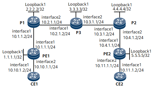
On the network shown in Figure 1, CE1 and CE2 belong to the same L3VPN. They access the public network through PE1 and PE2, respectively. Various types of services are transmitted between CE1 and CE2. Transmitting a large number of common services deteriorates the efficiency of transmitting important services. To prevent this problem, configure the CBTS function. This function allows traffic of a specific service class to be transmitted along a specified tunnel.
This example requires Tunnel1 to transmit important services and Tunnel2 to transmit other services.
Precautions
The destination IP address of a tunnel must be equal to the LSR ID of the egress of the tunnel.
Configuration Roadmap
The configuration roadmap is as follows:
Assign an IP address and its mask to each interface and configure a loopback interface address as an LSR ID on each node. In addition, configure an IGP to advertise routes.
Create an SR-MPLS TE tunnel in each TE-capable area, and specify a service class for packets that can be transmitted by the tunnel.
Enable MPLS LDP in the TE-incapable area, and configure a remote LDP peer for each edge node in the TE-capable area.
Configure the TE forwarding adjacency function.
Configure multi-field classification on nodes connected to the L3VPN as well as behavior aggregate classification on LDP over SR-MPLS TE links.
Data Preparation
To complete the configuration, you need the following data:
IS-IS process ID, level, network entity ID, and cost type
Policy that is used for triggering LSP establishment
Name and IP address of each remote LDP peer of P1 and P2
Link bandwidth attributes of each tunnel
Tunnel interface number, IP address, destination IP address, tunnel ID, tunnel signaling protocol, tunnel bandwidth, TE metric value, and link cost on P1 and P2
Multi-field classifier name and traffic policy name
Procedure
- Assign an IP address and its mask to each interface.
# Configure PE1.
<HUAWEI> system-view
[~HUAWEI] sysname PE1
[*HUAWEI] commit
[~PE1] interface loopback 1
[*PE1-LoopBack1] ip address 1.1.1.1 32
[*PE1-LoopBack1] quit
[*PE1] interface gigabitethernet0/1/0
[*PE1-GigabitEthernet0/1/0] ip address 10.1.1.1 24
[*PE1-GigabitEthernet0/1/0] quit
[*PE1] commit
# Configure P1.
<HUAWEI> system-view
[~HUAWEI] sysname P1
[*HUAWEI] commit
[~P1] interface loopback 1
[*P1-LoopBack1] ip address 2.2.2.2 32
[*P1-LoopBack1] quit
[*P1] interface gigabitethernet0/1/0
[*P1-GigabitEthernet0/1/0] ip address 10.1.1.2 24
[*P1-GigabitEthernet0/1/0] quit
[*P1] interface gigabitethernet0/1/8
[*P1-GigabitEthernet0/1/8] ip address 10.2.1.1 24
[*P1-GigabitEthernet0/1/8] quit
[*P1] commit
# Configure P2.
<HUAWEI> system-view
[~HUAWEI] sysname P2
[*HUAWEI] commit
[~P2] interface loopback 1
[*P2-LoopBack1] ip address 4.4.4.4 32
[*P2-LoopBack1] quit
[*P2] interface gigabitethernet0/1/0
[*P2-GigabitEthernet0/1/0] ip address 10.3.1.2 24
[*P2-GigabitEthernet0/1/0] quit
[*P2] interface gigabitethernet0/1/8
[*P2-GigabitEthernet0/1/8] ip address 10.4.1.2 24
[*P2-GigabitEthernet0/1/8] quit
[*P2] commit
# Configure P3.
<HUAWEI> system-view
[~HUAWEI] sysname P3
[*HUAWEI] commit
[~P3] interface loopback 1
[*P3-LoopBack1] ip address 3.3.3.3 32
[*P3-LoopBack1] quit
[*P3] interface gigabitethernet0/1/0
[*P3-GigabitEthernet0/1/0] ip address 10.2.1.2 24
[*P3-GigabitEthernet0/1/0] quit
[*P3] interface gigabitethernet0/1/8
[*P3-GigabitEthernet0/1/8] ip address 10.3.1.1 24
[*P3-GigabitEthernet0/1/8] quit
[*P3] commit
# Configure PE2.
<HUAWEI> system-view
[~HUAWEI] sysname PE2
[*HUAWEI] commit
[~PE2] interface loopback 1
[*PE2-LoopBack1] ip address 5.5.5.5 32
[*PE2-LoopBack1] quit
[*PE2] interface gigabitethernet0/1/0
[*PE2-GigabitEthernet0/1/0] ip address 10.4.1.1 24
[*PE2-GigabitEthernet0/1/0] quit
[*PE2] commit
- Enable IS-IS to advertise the route of the network segment connected to each interface and the host route destined for each LSR ID.
# Configure PE1.
[~PE1] isis 1
[*PE1-isis-1] cost-style wide
[*PE1-isis-1] network-entity 10.0000.0000.0001.00
[*PE1-isis-1] is-level level-2
[*PE1-isis-1] quit
[*PE1] interface gigabitethernet 0/1/0
[*PE1-GigabitEthernet0/1/0] isis enable 1
[*PE1-GigabitEthernet0/1/0] quit
[*PE1] interface loopback 1
[*PE1-LoopBack1] isis enable 1
[*PE1-LoopBack1] commit
[~PE1-LoopBack1] quit
# Configure P1.
[~P1] isis 1
[*P1-isis-1] cost-style wide
[*P1-isis-1] network-entity 10.0000.0000.0002.00
[*P1-isis-1] is-level level-2
[*P1-isis-1] quit
[*P1] interface gigabitethernet 0/1/0
[*P1-GigabitEthernet0/1/0] isis enable 1
[*P1-GigabitEthernet0/1/0] quit
[*P1] interface gigabitethernet 0/1/8
[*P1-GigabitEthernet0/1/8] isis enable 1
[*P1-GigabitEthernet0/1/8] quit
[*P1] interface loopback 1
[*P1-LoopBack1] isis enable 1
[*P1-LoopBack1] commit
[~P1-LoopBack1] quit
# Configure P2.
[~P2] isis 1
[*P2-isis-1] cost-style wide
[*P2-isis-1] network-entity 10.0000.0000.0003.00
[*P2-isis-1] is-level level-2
[*P2-isis-1] quit
[*P2] interface gigabitethernet 0/1/0
[*P2-GigabitEthernet0/1/0] isis enable 1
[*P2-GigabitEthernet0/1/0] quit
[*P2] interface gigabitethernet 0/1/8
[*P2-GigabitEthernet0/1/8] isis enable 1
[*P2-GigabitEthernet0/1/8] quit
[*P2] interface loopback 1
[*P2-LoopBack1] isis enable 1
[*P2-LoopBack1] commit
[~P2-LoopBack1] quit
# Configure P3.
[~P3] isis 1
[*P3-isis-1] cost-style wide
[*P3-isis-1] network-entity 10.0000.0000.0004.00
[*P3-isis-1] is-level level-2
[*P3-isis-1] quit
[*P3] interface gigabitethernet 0/1/0
[*P3-GigabitEthernet0/1/0] isis enable 1
[*P3-GigabitEthernet0/1/0] quit
[*P3] interface gigabitethernet 0/1/8
[*P3-GigabitEthernet0/1/8] isis enable 1
[*P3-GigabitEthernet0/1/8] quit
[*P3] interface loopback 1
[*P3-LoopBack1] isis enable 1
[*P3-LoopBack1] commit
[~P3-LoopBack1] quit
# Configure PE2.
[~PE2] isis 1
[*PE2-isis-1] cost-style wide
[*PE2-isis-1] network-entity 10.0000.0000.0005.00
[*PE2-isis-1] is-level level-2
[*PE2-isis-1] quit
[*PE2] interface gigabitethernet 0/1/0
[*PE2-GigabitEthernet0/1/0] isis enable 1
[*PE2-GigabitEthernet0/1/0] quit
[*PE2] interface loopback 1
[*PE2-LoopBack1] isis enable 1
[*PE2-LoopBack1] commit
[~PE2-LoopBack1] quit
After completing the preceding configurations, run the display ip routing-table command on each node to check that both PEs have learned routes from each other.
- Establish an MP-IBGP peer relationship between PEs.
# Configure PE1.
[~PE1] bgp 100
[~PE1-bgp] peer 5.5.5.5 as-number 100
[*PE1-bgp] peer 5.5.5.5 connect-interface loopback 1
[*PE1-bgp] ipv4-family vpnv4
[*PE1-bgp-af-vpnv4] peer 5.5.5.5 enable
[*PE1-bgp-af-vpnv4] commit
[~PE1-bgp-af-vpnv4] quit
[~PE1-bgp] quit
# Configure PE2.
[~PE2] bgp 100
[~PE2-bgp] peer 1.1.1.1 as-number 100
[*PE2-bgp] peer 1.1.1.1 connect-interface loopback 1
[*PE2-bgp] ipv4-family vpnv4
[*PE2-bgp-af-vpnv4] peer 1.1.1.1 enable
[*PE2-bgp-af-vpnv4] commit
[~PE2-bgp-af-vpnv4] quit
[~PE2-bgp] quit
After the configuration is complete, run the display bgp peer or display bgp vpnv4 all peer command on the PEs to check whether a BGP peer relationship has been established between the PEs. If the Established state is displayed in the command output, the BGP peer relationship has been established successfully. The following example uses the command output on PE1.
[~PE1] display bgp peer
 BGP local router ID : 1.1.1.1
 Local AS number : 100
 Total number of peers : 1          Peers in established state : 1
  Peer            V    AS  MsgRcvd  MsgSent     OutQ  Up/Down    State        PrefRcv
  5.5.5.5         4   100        2        6     0     00:00:12   Established   0
[~PE1] display bgp vpnv4 all peer
 BGP local router ID : 1.1.1.1
 Local AS number : 100
 Total number of peers : 1                 Peers in established state : 1
  Peer            V    AS  MsgRcvd  MsgSent    OutQ  Up/Down    State        PrefRcv
  5.5.5.5         4   100   12      18         0     00:09:38   Established   0
- Configure basic MPLS functions, and enable LDP between PE1 and P1 and between PE2 and P2.
# Configure PE1.
[~PE1] mpls lsr-id 1.1.1.1
[*PE1] mpls
[*PE1-mpls] lsp-trigger all
[*PE1-mpls] quit
[*PE1] mpls ldp
[*PE1-mpls-ldp] quit
[*PE1] interface gigabitethernet 0/1/0
[*PE1-GigabitEthernet0/1/0] mpls
[*PE1-GigabitEthernet0/1/0] mpls ldp
[*PE1-GigabitEthernet0/1/0] commit
[~PE1-GigabitEthernet0/1/0] quit
# Configure P1.
[~P1] mpls lsr-id 2.2.2.2
[*P1] mpls
[*P1-mpls] mpls te
[*P1-mpls] lsp-trigger all
[*P1-mpls] quit
[*P1] mpls ldp
[*P1-mpls-ldp] quit
[*P1] interface gigabitethernet 0/1/0
[*P1-GigabitEthernet0/1/0] mpls
[*P1-GigabitEthernet0/1/0] mpls ldp
[*P1-GigabitEthernet0/1/0] quit
[*P1] interface gigabitethernet 0/1/8
[*P1-GigabitEthernet0/1/8] mpls
[*P1-GigabitEthernet0/1/8] mpls te
[*P1-GigabitEthernet0/1/8] commit
[~P1-GigabitEthernet0/1/8] quit
# Configure P3.
[~P3] mpls lsr-id 3.3.3.3
[*P3] mpls
[*P3-mpls] mpls te
[*P3-mpls] quit
[*P3] interface gigabitethernet 0/1/0
[*P3-GigabitEthernet0/1/0] mpls
[*P3-GigabitEthernet0/1/0] mpls te
[*P3-GigabitEthernet0/1/0] quit
[*P3] interface gigabitethernet 0/1/8
[*P3-GigabitEthernet0/1/8] mpls
[*P3-GigabitEthernet0/1/8] mpls te
[*P3-GigabitEthernet0/1/8] commit
[~P3-GigabitEthernet0/1/8] quit
# Configure P2.
[~P2] mpls lsr-id 4.4.4.4
[*P2] mpls
[*P2-mpls] mpls te
[*P2-mpls] lsp-trigger all
[*P2-mpls] quit
[*P2] mpls ldp
[*P2-mpls-ldp] quit
[*P2] interface gigabitethernet 0/1/0
[*P2-GigabitEthernet0/1/0] mpls
[*P2-GigabitEthernet0/1/0] mpls te
[*P2-GigabitEthernet0/1/0] quit
[*P2] interface gigabitethernet 0/1/8
[*P2-GigabitEthernet0/1/8] mpls
[*P2-GigabitEthernet0/1/8] mpls ldp
[*P2-GigabitEthernet0/1/8] commit
[~P2-GigabitEthernet0/1/8] quit
# Configure PE2.
[~PE2] mpls lsr-id 5.5.5.5
[*PE2] mpls
[*PE2-mpls] lsp-trigger all
[*PE2-mpls] quit
[*PE2] mpls ldp
[*PE2-mpls-ldp] quit
[*PE2] interface gigabitethernet 0/1/0
[*PE2-GigabitEthernet0/1/0] mpls
[*PE2-GigabitEthernet0/1/0] mpls ldp
[*PE2-GigabitEthernet0/1/0] commit
[~PE2-GigabitEthernet0/1/0] quit
After you complete the preceding configurations, local LDP sessions are successfully established between PE1 and P1 and between PE2 and P2.
# Run the display mpls ldp session command on PE1, P1, P2, or PE2 to view LDP session information.
[~PE1] display mpls ldp session
 LDP Session(s) in Public Network
 Codes: LAM(Label Advertisement Mode), SsnAge Unit(DDDD:HH:MM)
 An asterisk (*) before a session means the session is being deleted.
--------------------------------------------------------------------------
 PeerID             Status      LAM  SsnRole  SsnAge       KASent/Rcv
--------------------------------------------------------------------------
 2.2.2.2:0          Operational DU   Passive  0000:00:05   23/23
--------------------------------------------------------------------------
TOTAL: 1 Session(s) Found.
# Run the display mpls ldp peer command to view LDP peer information. The following example uses the command output on PE1.
[~PE1] display mpls ldp peer
 LDP Peer Information in Public network
 An asterisk (*) before a peer means the peer is being deleted.
 -------------------------------------------------------------------------
 PeerID                 TransportAddress   DiscoverySource
 -------------------------------------------------------------------------
 2.2.2.2:0              2.2.2.2            GigabitEthernet0/1/0
 -------------------------------------------------------------------------
TOTAL: 1 Peer(s) Found.
# Run the display mpls lsp command to view LDP LSP information. The following example uses the command output on PE1.
[~PE1] display mpls lsp
Flag after Out IF: (I) - RLFA Iterated LSP, (I*) - Normal and RLFA Iterated LSP
Flag after LDP FRR: (L) - Logic FRR LSP
----------------------------------------------------------------------
                 LSP Information: LDP LSP
----------------------------------------------------------------------
FEC                In/Out Label  In/Out IF                      Vrf Name
1.1.1.1/32         3/NULL        GE0/1/0/-
2.2.2.2/32         NULL/3        -/GE0/1/0
2.2.2.2/32         1024/3        -/GE0/1/0
10.1.1.0/24        3/NUL         GE0/1/0/-
10.2.1.0/24        NULL/3        -/GE0/1/0
10.2.1.0/24        1025/3        -/GE0/1/0
- Set up a remote LDP session between P1 and P2.
# Configure P1.
[~P1] mpls ldp remote-peer lsrd
[*P1-mpls-ldp-remote-lsrd] remote-ip 4.4.4.4
[*P1-mpls-ldp-remote-lsrd] commit
[~P1-mpls-ldp-remote-lsrd] quit
# Configure P2.
[~P2] mpls ldp remote-peer lsrb
[*P2-mpls-ldp-remote-lsrb] remote-ip 2.2.2.2
[*P2-mpls-ldp-remote-lsrb] commit
[~P2-mpls-ldp-remote-lsrb] quit
After you complete the preceding configurations, a remote LDP session is set up between P1 and P2. Run the display mpls ldp remote-peer command on P1 or P2 to view information about the remote session entity. The following example uses the command output on P1.
[~P1] display mpls ldp remote-peer lsrd LDP Remote Entity Information ------------------------------------------------------------------------------ Remote Peer Name: lsrd Description : ---- Remote Peer IP : 4.4.4.4 LDP ID : 2.2.2.2:0 Transport Address : 2.2.2.2 Entity Status : Active Configured Keepalive Hold Timer : 45 Sec Configured Keepalive Send Timer : ---- Configured Hello Hold Timer : 45 Sec Negotiated Hello Hold Timer : 45 Sec Configured Hello Send Timer : ---- Configured Delay Timer : ---- Hello Packet sent/received : 425/382 Label Advertisement Mode : Downstream Unsolicited Auto-config : ---- Session-Protect effect : NO Session-Protect Duration : ---- Session-Protect Remain : ---- ------------------------------------------------------------------------------ TOTAL: 1 Remote-Peer(s) Found. - Configure bandwidth attributes for the outbound interface of each TE tunnel.
# Configure P1.
[~P1] interface gigabitethernet 0/1/8
[~P1-GigabitEthernet0/1/8] mpls te bandwidth max-reservable-bandwidth 20000
[*P1-GigabitEthernet0/1/8] mpls te bandwidth bc0 20000
[*P1-GigabitEthernet0/1/8] commit
[~P1-GigabitEthernet0/1/8] quit
# Configure P3.
[~P3] interface gigabitethernet 0/1/0
[~P3-GigabitEthernet0/1/0] mpls te bandwidth max-reservable-bandwidth 20000
[*P3-GigabitEthernet0/1/0] mpls te bandwidth bc0 20000
[*P3-GigabitEthernet0/1/0] quit
[*P3] interface gigabitethernet 0/1/8
[*P3-GigabitEthernet0/1/8] mpls te bandwidth max-reservable-bandwidth 20000
[*P3-GigabitEthernet0/1/8] mpls te bandwidth bc0 20000
[*P3-GigabitEthernet0/1/8] commit
[~P3-GigabitEthernet0/1/8] quit
# Configure P2.
[~P2] interface gigabitethernet 0/1/0
[~P2-GigabitEthernet0/1/0] mpls te bandwidth max-reservable-bandwidth 20000
[*P2-GigabitEthernet0/1/0] mpls te bandwidth bc0 20000
[*P2-GigabitEthernet0/1/0] commit
[~P2-GigabitEthernet0/1/0] quit
- Configure L3VPN access on PE1 and PE2 and multi-field classification on the inbound interface of PE1.
# Configure PE1.
[~PE1] ip vpn-instance VPNA
[*PE1-vpn-instance-VPNA] ipv4-family
[*PE1-vpn-instance-VPNA-af-ipv4] route-distinguisher 100:1
[*PE1-vpn-instance-VPNA-af-ipv4] vpn-target 111:1 both
[*PE1-vpn-instance-VPNA-af-ipv4] quit
[*PE1-vpn-instance-VPNA] quit
[*PE1] interface gigabitethernet 0/1/8
[*PE1-GigabitEthernet0/1/8] ip binding vpn-instance VPNA
[*PE1-GigabitEthernet0/1/8] ip address 10.10.1.1 24
[*PE1-GigabitEthernet0/1/8] quit
[*PE1] acl 2001
[*PE1-acl4-basic-2001] rule 10 permit source 10.40.0.0 0.0.255.255
[*PE1-acl4-basic-2001] quit
[*PE1] acl 2002
[*PE1-acl4-basic-2002] rule 20 permit source 10.50.0.0 0.0.255.255
[*PE1-acl4-basic-2002] quit
[*PE1] traffic classifier service1
[*PE1-classifier-service1] if-match acl 2001
[*PE1-classifier-service1] commit
[~PE1-classifier-service1] quit
[~PE1] traffic behavior behavior1
[*PE1-behavior-behavior1] service-class af1 color green
[*PE1-behavior-behavior1] commit
[~PE1-behavior-behavior1] quit
[~PE1] traffic classifier service2
[*PE1-classifier-service2] if-match acl 2002
[*PE1-classifier-service2] commit
[~PE1-classifier-service2] quit
[~PE1] traffic behavior behavior2
[*PE1-behavior-behavior2] service-class af2 color green
[*PE1-behavior-behavior2] commit
[~PE1-behavior-behavior2] quit
[~PE1] traffic policy test
[*PE1-trafficpolicy-test] classifier service1 behavior behavior1
[*PE1-trafficpolicy-test] classifier service2 behavior behavior2
[*PE1-trafficpolicy-test] commit
[~PE1-trafficpolicy-test] quit
[~PE1] interface gigabitethernet 0/1/8
[~PE1-GigabitEthernet0/1/8] traffic-policy test inbound
[*PE1-GigabitEthernet0/1/8] commit
[~PE1-GigabitEthernet0/1/8] quit
# Configure PE2.
[~PE2] ip vpn-instance VPNB
[*PE2-vpn-instance-VPNB] ipv4-family
[*PE2-vpn-instance-VPNB-af-ipv4] route-distinguisher 200:1
[*PE2-vpn-instance-VPNB-af-ipv4] vpn-target 111:1 both
[*PE2-vpn-instance-VPNB-af-ipv4] quit
[*PE2-vpn-instance-VPNB] quit
[*PE2] interface gigabitethernet 0/1/8
[*PE2-GigabitEthernet0/1/8] ip binding vpn-instance VPNB
[*PE2-GigabitEthernet0/1/8] ip address 10.11.1.1 24
[*PE2-GigabitEthernet0/1/8] commit
[~PE2-GigabitEthernet0/1/8] quit
- Configure behavior aggregate classification on interfaces connecting PE1 and P1.
# Configure PE1.
[~PE1] interface gigabitethernet 0/1/0
[~PE1-GigabitEthernet0/1/0] trust upstream default
[*PE1-GigabitEthernet0/1/0] commit
[~PE1-GigabitEthernet0/1/0] quit
# Configure P1.
[~P1] interface gigabitethernet 0/1/0
[~P1-GigabitEthernet0/1/0] trust upstream default
[*P1-GigabitEthernet0/1/0] commit
[~P1-GigabitEthernet0/1/0] quit
- Enable SR and configure an explicit path.
In this example, the explicit path is used to establish an SR-MPLS TE tunnel.

The SRGB range varies according to the device. The range specified in this example is for reference only.
# Configure P1.
[~P1] segment-routing
[*P1-segment-routing] quit
[*P1] isis 1
[*P1-isis-1] traffic-eng level-2
[*P1-isis-1] segment-routing mpls
[*P1-isis-1] segment-routing global-block 16000 19000
[*P1-isis-1] commit
[~P1-isis-1] quit
# Configure P2.
[~P2] segment-routing
[*P2-segment-routing] quit
[*P2] isis 1
[*P2-isis-1] traffic-eng level-2
[*P2-isis-1] segment-routing mpls
[*P2-isis-1] segment-routing global-block 16000 19000
[*P2-isis-1] commit
[~P2-isis-1] quit
# Configure P3.
[~P3] segment-routing
[*P3-segment-routing] quit
[*P3] isis 1
[*P3-isis-1] traffic-eng level-2
[*P3-isis-1] segment-routing mpls
[*P3-isis-1] segment-routing global-block 16000 19000
[*P3-isis-1] commit
[~P3-isis-1] quit
# Display the adjacency SID of each node.
[~P1] display segment-routing adjacency mpls forwarding

            Segment Routing Adjacency MPLS Forwarding Information

Label     Interface         NextHop          Type        MPLSMtu   Mtu
-----------------------------------------------------------------------------
48091     GE0/1/0           10.1.1.1         ISIS-V4     ---       1500
48092     GE0/1/8           10.2.1.2         ISIS-V4     ---       1500

Total information(s): 2
[~P3] display segment-routing adjacency mpls forwarding

            Segment Routing Adjacency MPLS Forwarding Information

Label     Interface         NextHop          Type        MPLSMtu   Mtu
-----------------------------------------------------------------------------
48090     GE0/1/0           10.2.1.1         ISIS-V4     ---       1500
48091     GE0/1/8           10.3.1.2         ISIS-V4     ---       1500

Total information(s): 2
[~P2] display segment-routing adjacency mpls forwarding

            Segment Routing Adjacency MPLS Forwarding Information

Label     Interface         NextHop          Type        MPLSMtu   Mtu
-----------------------------------------------------------------------------
48090     GE0/1/8           10.4.1.1         ISIS-V4     ---       1500
48091     GE0/1/0           10.3.1.1         ISIS-V4     ---       1500

Total information(s): 2
# Configure an explicit path from P1 to P2.
[~P1] explicit-path p1_p2
[*P1-explicit-path-p1_p2] next sid label 48092 type adjacency
[*P1-explicit-path-p1_p2] next sid label 48091 type adjacency
[*P1-explicit-path-p1_p2] commit
[~P1-explicit-path-p1_p2] quit
# Configure an explicit path from P2 to P1.
[~P2] explicit-path p2_p1
[*P2-explicit-path-p2_p1] next sid label 48091 type adjacency
[*P2-explicit-path-p2_p1] next sid label 48090 type adjacency
[*P2-explicit-path-p2_p1] commit
[~P2-explicit-path-p2_p1] quit
- Configure TE tunnels from P1 to P2 and set a service class for each type of packet that can be transmitted by the tunnels.
Run the mpls te service-class { service-class & <1-8> | default } command to set a service class for packets that are allowed to pass through tunnels.
# On P1, enable the IGP shortcut function on each tunnel interface and adjust the metric value of the forwarding adjacency function to ensure that traffic destined for P2 or PE2 passes through the corresponding tunnel.
[~P1] interface Tunnel1
[*P1-Tunnel1] ip address unnumbered interface LoopBack1
[*P1-Tunnel1] tunnel-protocol mpls te
[*P1-Tunnel1] destination 4.4.4.4
[*P1-Tunnel1] mpls te tunnel-id 100
[*P1-Tunnel1] mpls te bandwidth ct0 10000
[*P1-Tunnel1] mpls te igp shortcut
[*P1-Tunnel1] mpls te igp metric absolute 1
[*P1-Tunnel1] isis enable 1
[*P1-Tunnel1] mpls te signal-protocol segment-routing
[*P1-Tunnel1] mpls te path explicit-path p1_p2
[*P1-Tunnel1] mpls te service-class af1 af2
[*P1-Tunnel1] quit
[*P1] interface Tunnel2
[*P1-Tunnel2] ip address unnumbered interface LoopBack1
[*P1-Tunnel2] tunnel-protocol mpls te
[*P1-Tunnel2] destination 4.4.4.4
[*P1-Tunnel2] mpls te tunnel-id 200
[*P1-Tunnel2] mpls te bandwidth ct0 10000
[*P1-Tunnel2] mpls te igp shortcut
[*P1-Tunnel2] mpls te igp metric absolute 1
[*P1-Tunnel2] isis enable 1
[*P1-Tunnel2] mpls te signal-protocol segment-routing
[*P1-Tunnel2] mpls te path explicit-path p1_p2
[*P1-Tunnel2] mpls te service-class default
[*P1-Tunnel2] quit
[*P1] commit
- Configure a tunnel from P2 to P1.
# On P2, enable the forwarding adjacency function on each tunnel interface and adjust the metric value of the forwarding adjacency function to ensure that traffic destined for PE1 or P1 passes through the tunnel.
[~P2] interface Tunnel1
[*P2-Tunnel1] ip address unnumbered interface LoopBack1
[*P2-Tunnel1] tunnel-protocol mpls te
[*P2-Tunnel1] destination 2.2.2.2
[*P2-Tunnel1] mpls te tunnel-id 101
[*P2-Tunnel1] mpls te bandwidth ct0 10000
[*P2-Tunnel1] mpls te igp shortcut
[*P2-Tunnel1] mpls te igp metric absolute 1
[*P2-Tunnel1] isis enable 1
[*P2-Tunnel1] mpls te signal-protocol segment-routing
[*P2-Tunnel1] mpls te path explicit-path p2_p1
[*P2-Tunnel1] quit
[*P2] commit
- Establish an EBGP peer relationship between each PE and its connected CE.
# Configure CE1.
<HUAWEI> system-view
[~HUAWEI] sysname CE1
[*HUAWEI] commit
[~CE1] interface gigabitethernet0/1/0
[~CE1-GigabitEthernet0/1/0] ip address 10.10.1.2 24
[*CE1-GigabitEthernet0/1/0] quit
[*CE1] bgp 65410
[*CE1-bgp] peer 10.10.1.1 as-number 100
[*CE1-bgp] import-route direct
[*CE1-bgp] quit
[*CE1] commit
The configuration of CE2 is similar to the configuration of CE1. For configuration details, see Configuration Files in this section.
# Configure PE1.
[~PE1] bgp 100
[*PE1-bgp] ipv4-family vpn-instance VPNA
[*PE1-bgp-VPNA] peer 10.10.1.2 as-number 65410
[*PE1-bgp-VPNA] commit
[~PE1-bgp-VPNA] quit
[~PE1-bgp] quit
The configuration of PE2 is similar to the configuration of PE1. For configuration details, see Configuration Files in this section.
After the configuration is complete, run the display bgp vpnv4 vpn-instance peer command on the PEs to check whether BGP peer relationships have been established between the PEs and CEs. If the Established state is displayed in the command output, the BGP peer relationships have been established successfully.
- Verify the configuration.
# Run the ping command on P1 to check the connectivity of each SR-MPLS TE tunnel. For example:
[~P1] ping lsp segment-routing te Tunnel 1
  LSP PING FEC: SEGMENT ROUTING TE TUNNEL IPV4 SESSION QUERY Tunnel1 : 100  data bytes, press CTRL_C to break
    Reply from 4.4.4.4: bytes=100 Sequence=1 time=20 ms
    Reply from 4.4.4.4: bytes=100 Sequence=2 time=16 ms
    Reply from 4.4.4.4: bytes=100 Sequence=3 time=16 ms
    Reply from 4.4.4.4: bytes=100 Sequence=4 time=12 ms
    Reply from 4.4.4.4: bytes=100 Sequence=5 time=12 ms

  --- FEC: SEGMENT ROUTING TE TUNNEL IPV4 SESSION QUERY Tunnel1 ping statistics ---
    5 packet(s) transmitted
    5 packet(s) received
    0.00% packet loss
    round-trip min/avg/max = 12/15/20 ms
[~P1] ping lsp segment-routing te Tunnel 2
  LSP PING FEC: SEGMENT ROUTING TE TUNNEL IPV4 SESSION QUERY Tunnel2 : 100  data bytes, press CTRL_C to break
    Reply from 4.4.4.4: bytes=100 Sequence=1 time=17 ms
    Reply from 4.4.4.4: bytes=100 Sequence=2 time=17 ms
    Reply from 4.4.4.4: bytes=100 Sequence=3 time=12 ms
    Reply from 4.4.4.4: bytes=100 Sequence=4 time=12 ms
    Reply from 4.4.4.4: bytes=100 Sequence=5 time=14 ms

  --- FEC: SEGMENT ROUTING TE TUNNEL IPV4 SESSION QUERY Tunnel2 ping statistics ---
    5 packet(s) transmitted
    5 packet(s) received
    0.00% packet loss
    round-trip min/avg/max = 12/14/17 ms
# Check information about LDP LSP establishment on each PE. The following example uses the command output on PE1.
[~PE1] display mpls lsp
Flag after Out IF: (I) - RLFA Iterated LSP, (I*) - Normal and RLFA Iterated LSP
Flag after LDP FRR: (L) - Logic FRR LSP
-------------------------------------------------------------------------------
                 LSP Information: LDP LSP
-------------------------------------------------------------------------------
FEC                In/Out Label    In/Out IF                      Vrf Name
1.1.1.1/32         3/NULL          -/-
2.2.2.2/32         NULL/3          -/GE0/1/8
2.2.2.2/32         48151/3         -/GE0/1/8
3.3.3.3/32         NULL/48150      -/GE0/1/8
3.3.3.3/32         48152/48150     -/GE0/1/8
4.4.4.4/32         NULL/48153      -/GE0/1/8
4.4.4.4/32         48155/48153     -/GE0/1/8
5.5.5.5/32         NULL/48155      -/GE0/1/8
5.5.5.5/32         48157/48155     -/GE0/1/8
10.1.1.0/24        3/NULL          -/-
10.2.1.0/24        NULL/3          -/GE0/1/8
10.2.1.0/24        48153/3         -/GE0/1/8
10.3.1.0/24        NULL/48151      -/GE0/1/8
10.3.1.0/24        48154/48151     -/GE0/1/8
10.4.1.0/24        NULL/48154      -/GE0/1/8
10.4.1.0/24        48156/48154     -/GE0/1/8
-------------------------------------------------------------------------------
                 LSP Information: BGP LSP
-------------------------------------------------------------------------------
FEC                In/Out Label    In/Out IF                      Vrf Name
-/32               48090/NULL      -/-                             VPNA
Configuration Files
PE1 configuration file
#
sysname PE1
#
ip vpn-instance VPNA
 ipv4-family
  route-distinguisher 100:1
  apply-label per-instance
  vpn-target 111:1 export-extcommunity
  vpn-target 111:1 import-extcommunity
#
mpls lsr-id 1.1.1.1
#
mpls
 lsp-trigger all
#
mpls ldp
 #
 ipv4-family
#
acl number 2001
 rule 10 permit source 10.40.0.0 0.0.255.255
#
acl number 2002
 rule 20 permit source 10.50.0.0 0.0.255.255
#
traffic classifier service1 operator or
 if-match acl 2001
#
traffic classifier service2 operator or
 if-match acl 2002
#
traffic behavior behavior1
 service-class af1 color green
#
traffic behavior behavior2
 service-class af2 color green
#
traffic policy test
 share-mode
 classifier service1 behavior behavior1 precedence 1
 classifier service2 behavior behavior2 precedence 2
#
segment-routing
#
isis 1
 is-level level-2
 cost-style wide
 network-entity 10.0000.0000.0001.00
#
interface GigabitEthernet0/1/0
 undo shutdown
 ip address 10.1.1.1 255.255.255.0
 isis enable 1
 mpls
 mpls ldp
 trust upstream default
#
interface GigabitEthernet0/1/8
 undo shutdown
 ip binding vpn-instance VPNA
 ip address 10.10.1.1 255.255.255.0
 traffic-policy test inbound
#
interface LoopBack1
 ip address 1.1.1.1 255.255.255.255
 isis enable 1
#
bgp 100
 peer 5.5.5.5 as-number 100
 peer 5.5.5.5 connect-interface LoopBack1
 #
 ipv4-family unicast
  undo synchronization
  peer 5.5.5.5 enable
 #
 ipv4-family vpnv4
  policy vpn-target
  peer 5.5.5.5 enable
 #
 ipv4-family vpn-instance VPNA
  peer 10.10.1.2 as-number 65410
#
return
P1 configuration file
#
sysname P1
#
mpls lsr-id 2.2.2.2
#
mpls
 mpls te
 lsp-trigger all
#
explicit-path p1_p2
 next sid label 48092 type adjacency
 next sid label 48091 type adjacency
#
mpls ldp
 #
 ipv4-family
#
mpls ldp remote-peer lsrd
 remote-ip 4.4.4.4
#
segment-routing
#
isis 1
 is-level level-2
 cost-style wide
 network-entity 10.0000.0000.0002.00
 traffic-eng level-2
 segment-routing mpls
 segment-routing global-block 16000 19000
#
interface GigabitEthernet0/1/0
 undo shutdown
 ip address 10.1.1.2 255.255.255.0
 isis enable 1
 mpls
 mpls ldp
 trust upstream default
#
interface GigabitEthernet0/1/8
 undo shutdown
 ip address 10.2.1.1 255.255.255.0
 isis enable 1
 mpls
 mpls te
 mpls te bandwidth max-reservable-bandwidth 20000
 mpls te bandwidth bc0 20000
#
interface LoopBack1
 ip address 2.2.2.2 255.255.255.255
 isis enable 1
#
interface Tunnel1
 ip address unnumbered interface LoopBack1
 tunnel-protocol mpls te
 isis enable 1
 destination 4.4.4.4
 mpls te signal-protocol segment-routing
 mpls te igp shortcut
 mpls te igp metric absolute 1
 mpls te bandwidth ct0 10000
 mpls te tunnel-id 100
 mpls te path explicit-path p1_p2
 mpls te service-class af1 af2
#
interface Tunnel2
 ip address unnumbered interface LoopBack1
 tunnel-protocol mpls te
 isis enable 1
 destination 4.4.4.4
 mpls te signal-protocol segment-routing
 mpls te igp shortcut
 mpls te igp metric absolute 1
 mpls te bandwidth ct0 10000
 mpls te tunnel-id 200
 mpls te path explicit-path p1_p2
 mpls te service-class default
#
return
P3 configuration file
#
sysname P3
#
mpls lsr-id 3.3.3.3
#
mpls
 mpls te
#
segment-routing
#
isis 1
 is-level level-2
 cost-style wide
 network-entity 10.0000.0000.0004.00
 traffic-eng level-2
 segment-routing mpls
 segment-routing global-block 16000 19000
#
interface GigabitEthernet0/1/0
 undo shutdown
 ip address 10.2.1.2 255.255.255.0
 isis enable 1
 mpls
 mpls te
 mpls te bandwidth max-reservable-bandwidth 20000
 mpls te bandwidth bc0 20000
#
interface GigabitEthernet0/1/8
 undo shutdown
 ip address 10.3.1.1 255.255.255.0
 isis enable 1
 mpls
 mpls te
 mpls te bandwidth max-reservable-bandwidth 20000
 mpls te bandwidth bc0 20000
#
interface LoopBack1
 ip address 3.3.3.3 255.255.255.255
 isis enable 1
#
return
P2 configuration file
#
sysname P2
#
mpls lsr-id 4.4.4.4
#
mpls
 mpls te
 lsp-trigger all
#
explicit-path p2_p1
 next sid label 48091 type adjacency
 next sid label 48090 type adjacency
#
mpls ldp
 #
 ipv4-family
#
mpls ldp remote-peer lsrb
 remote-ip 2.2.2.2
#
segment-routing
#
isis 1
 is-level level-2
 cost-style wide
 network-entity 10.0000.0000.0003.00
 traffic-eng level-2
 segment-routing mpls
 segment-routing global-block 16000 19000
#
interface GigabitEthernet0/1/0
 undo shutdown
 ip address 10.3.1.2 255.255.255.0
 isis enable 1
 mpls
 mpls te
 mpls te bandwidth max-reservable-bandwidth 20000
 mpls te bandwidth bc0 20000
#
interface GigabitEthernet0/1/8
 undo shutdown
 ip address 10.4.1.2 255.255.255.0
 isis enable 1
 mpls
 mpls ldp
#
interface LoopBack1
 ip address 4.4.4.4 255.255.255.255
 isis enable 1
#
interface Tunnel1
 ip address unnumbered interface LoopBack1
 tunnel-protocol mpls te
 isis enable 1
 destination 2.2.2.2
 mpls te signal-protocol segment-routing
 mpls te igp shortcut
 mpls te igp metric absolute 1
 mpls te bandwidth ct0 10000
 mpls te tunnel-id 101
 mpls te path explicit-path p2_p1
#
return
PE2 configuration file
#
sysname PE2
#
ip vpn-instance VPNB
 ipv4-family
  route-distinguisher 200:1
  apply-label per-instance
  vpn-target 111:1 export-extcommunity
  vpn-target 111:1 import-extcommunity
#
mpls lsr-id 5.5.5.5
#
mpls
 lsp-trigger all
#
mpls ldp
#
segment-routing
#
isis 1
 is-level level-2
 cost-style wide
 network-entity 10.0000.0000.0005.00
#
interface GigabitEthernet0/1/0
 undo shutdown
 ip address 10.4.1.1 255.255.255.0
 isis enable 1
 mpls
 mpls ldp
#
interface GigabitEthernet0/1/8
 undo shutdown
 ip binding vpn-instance VPNB
 ip address 10.11.1.1 255.255.255.0
#
interface LoopBack1
 ip address 5.5.5.5 255.255.255.255
 isis enable 1
#
bgp 100
 peer 1.1.1.1 as-number 100
 peer 1.1.1.1 connect-interface LoopBack1
 #
 ipv4-family unicast
  undo synchronization
  peer 1.1.1.1 enable
 #
 ipv4-family vpnv4
  policy vpn-target
  peer 1.1.1.1 enable
 #
 ipv4-family vpn-instance VPNB
  peer 10.11.1.2 as-number 65420
#
return
CE1 configuration file
#
sysname CE1
#
interface GigabitEthernet0/1/0
 undo shutdown
 ip address 10.10.1.2 255.255.255.0
#
bgp 65410
 peer 10.10.1.1 as-number 100
 #
 ipv4-family unicast
  undo synchronization
  import-route direct
  peer 10.10.1.1 enable
#
return
CE2 configuration file
#
sysname CE2
#
interface GigabitEthernet0/1/0
 undo shutdown
 ip address 10.11.1.2 255.255.255.0
#
bgp 65420
 peer 10.11.1.1 as-number 100
 #
 ipv4-family unicast
  undo synchronization
  import-route direct
  peer 10.11.1.1 enable
#
return