Example for Configuring DSCP-Based IP Service Recursion to SR-MPLS TE Tunnels
This section provides an example for configuring IP service recursion to SR-MPLS TE tunnels based on the differentiated services code point (DSCP) values of IP packets.
Networking Requirements
In SR-MPLS TE scenarios, you can configure the class-of-service-based tunnel selection (CBTS) function to allow traffic of a specific service class to be transmitted along a specified tunnel. However, with the increase of service classes, the CBTS function is gradually incapable of meeting service requirements. Similar to the CBTS function, DSCP-based IP service recursion steers IPv4 or IPv6 packets into SR-MPLS TE tunnels based on the DSCP values of the packets.
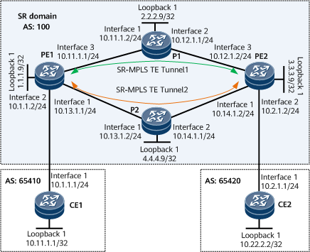
CE1 and CE2 belong to vpna. The VPN target used by vpna is 111:1.
- Two SR-MPLS TE tunnels (tunnel 1 and tunnel 2) are created between PE1 and PE2.
There are multiple types of services between CE1 and CE2. To ensure the forwarding quality of important services, you can configure the services to recurse to SR-MPLS TE tunnels based on the DSCP values of IP packets.
This example requires Tunnel1 to transmit services with DSCP values ranging from 0 to 10 and Tunnel2 to transmit other services by default.
Precautions
If a VPN instance is bound to a PE interface connected to a CE, Layer 3 configurations, such as IP address and routing protocol configurations, on this interface are automatically deleted. If needed, these items need to be reconfigured.
Configuration Roadmap
The configuration roadmap is as follows:
Configure IS-IS on the backbone network for the PEs to communicate.
Enable MPLS on the backbone network and configure SR and static adjacency labels.
Configure SR-MPLS TE tunnels between the PEs.
Establish an MP-IBGP peer relationship between the PEs.
Configure a VPN instance on each PE, enable the IPv4 address family for the instance, and bind the instance to the PE interface connecting the PE to a CE.
- Establish an EBGP peer relationship between each pair of a CE and a PE.
Configure a tunnel selection policy on each PE and set the number of tunnels participating in load balancing to 2, indicating that Tunnel1 and Tunnel2 balance service traffic.
- On each PE, configure tunnel 1 to transmit services with DSCP values ranging from 0 to 10 and tunnel 2 to transmit other services.
Data Preparation
To complete the configuration, you need the following data:
MPLS LSR IDs on the PEs and Ps
VPN target and RD of vpna
Procedure
- Configure interface IP addresses.
# Configure PE1.
<HUAWEI> system-view
[~HUAWEI] sysname PE1
[*HUAWEI] commit
[~PE1] interface loopback 1
[*PE1-LoopBack1] ip address 1.1.1.9 32
[*PE1-LoopBack1] quit
[*PE1] interface gigabitethernet0/1/0
[*PE1-GigabitEthernet0/1/0] ip address 10.13.1.1 24
[*PE1-GigabitEthernet0/1/0] quit
[*PE1] interface gigabitethernet0/1/16
[*PE1-GigabitEthernet0/1/16] ip address 10.11.1.1 24
[*PE1-GigabitEthernet0/1/16] quit
[*PE1] commit
# Configure P1.
<HUAWEI> system-view
[~HUAWEI] sysname P1
[*HUAWEI] commit
[~P1] interface loopback 1
[*P1-LoopBack1] ip address 2.2.2.9 32
[*P1-LoopBack1] quit
[*P1] interface gigabitethernet0/1/0
[*P1-GigabitEthernet0/1/0] ip address 10.11.1.2 24
[*P1-GigabitEthernet0/1/0] quit
[*P1] interface gigabitethernet0/1/8
[*P1-GigabitEthernet0/1/8] ip address 10.12.1.1 24
[*P1-GigabitEthernet0/1/8] quit
[*P1] commit
# Configure PE2.
<HUAWEI> system-view
[~HUAWEI] sysname PE2
[*HUAWEI] commit
[~PE2] interface loopback 1
[*PE2-LoopBack1] ip address 3.3.3.9 32
[*PE2-LoopBack1] quit
[*PE2] interface gigabitethernet0/1/0
[*PE2-GigabitEthernet0/1/0] ip address 10.14.1.2 24
[*PE2-GigabitEthernet0/1/0] quit
[*PE2] interface gigabitethernet0/1/16
[*PE2-GigabitEthernet0/1/16] ip address 10.12.1.2 24
[*PE2-GigabitEthernet0/1/16] quit
[*PE2] commit
# Configure P2.
<HUAWEI> system-view
[~HUAWEI] sysname P2
[*HUAWEI] commit
[~P2] interface loopback 1
[*P2-LoopBack1] ip address 4.4.4.9 32
[*P2-LoopBack1] quit
[*P2] interface gigabitethernet0/1/0
[*P2-GigabitEthernet0/1/0] ip address 10.13.1.2 24
[*P2-GigabitEthernet0/1/0] quit
[*P2] interface gigabitethernet0/1/8
[*P2-GigabitEthernet0/1/8] ip address 10.14.1.1 24
[*P2-GigabitEthernet0/1/8] quit
[*P2] commit
- Configure an IGP on the backbone network for the PEs and Ps to communicate. The following example uses IS-IS.
# Configure PE1.
[~PE1] isis 1
[*PE1-isis-1] is-level level-1
[*PE1-isis-1] network-entity 10.0000.0000.0001.00
[*PE1-isis-1] quit
[*PE1] interface loopback 1
[*PE1-LoopBack1] isis enable 1
[*PE1-LoopBack1] quit
[*PE1] interface gigabitethernet0/1/0
[*PE1-GigabitEthernet0/1/0] isis enable 1
[*PE1-GigabitEthernet0/1/0] quit
[*PE1] interface gigabitethernet0/1/16
[*PE1-GigabitEthernet0/1/16] isis enable 1
[*PE1-GigabitEthernet0/1/16] quit
[*PE1] commit
# Configure P1.
[~P1] isis 1
[*P1-isis-1] is-level level-1
[*P1-isis-1] network-entity 10.0000.0000.0002.00
[*P1-isis-1] quit
[*P1] interface loopback 1
[*P1-LoopBack1] isis enable 1
[*P1-LoopBack1] quit
[*P1] interface gigabitethernet0/1/0
[*P1-GigabitEthernet0/1/0] isis enable 1
[*P1-GigabitEthernet0/1/0] quit
[*P1] interface gigabitethernet0/1/8
[*P1-GigabitEthernet0/1/8] isis enable 1
[*P1-GigabitEthernet0/1/8] quit
[*P1] commit
# Configure PE2.
[~PE2] isis 1
[*PE2-isis-1] is-level level-1
[*PE2-isis-1] network-entity 10.0000.0000.0003.00
[*PE2-isis-1] quit
[*PE2] interface loopback 1
[*PE2-LoopBack1] isis enable 1
[*PE2-LoopBack1] quit
[*PE2] interface gigabitethernet0/1/16
[*PE2-GigabitEthernet0/1/16] isis enable 1
[*PE2-GigabitEthernet0/1/16] quit
[*PE2] interface gigabitethernet0/1/0
[*PE2-GigabitEthernet0/1/0] isis enable 1
[*PE2-GigabitEthernet0/1/0] quit
[*PE2] commit
# Configure P2.
[~P2] isis 1
[*P2-isis-1] is-level level-1
[*P2-isis-1] network-entity 10.0000.0000.0004.00
[*P2-isis-1] quit
[*P2] interface loopback 1
[*P2-LoopBack1] isis enable 1
[*P2-LoopBack1] quit
[*P2] interface gigabitethernet0/1/0
[*P2-GigabitEthernet0/1/0] isis enable 1
[*P2-GigabitEthernet0/1/0] quit
[*P2] interface gigabitethernet0/1/8
[*P2-GigabitEthernet0/1/8] isis enable 1
[*P2-GigabitEthernet0/1/8] quit
[*P2] commit
- Configure basic MPLS functions on the backbone network.
# Configure PE1.
[~PE1] mpls lsr-id 1.1.1.9
[*PE1] mpls
[*PE1-mpls] mpls te
[*PE1-mpls] commit
[~PE1-mpls] quit
# Configure P1.
[~P1] mpls lsr-id 2.2.2.9
[*P1] mpls
[*P1-mpls] mpls te
[*P1-mpls] commit
[~P1-mpls] quit
# Configure PE2.
[~PE2] mpls lsr-id 3.3.3.9
[*PE2] mpls
[*PE2-mpls] mpls te
[*PE2-mpls] commit
[~PE2-mpls] quit
# Configure P2.
[~P2] mpls lsr-id 4.4.4.9
[*P2] mpls
[*P2-mpls] mpls te
[*P2-mpls] commit
[~P2-mpls] quit
- Configure SR on the backbone network.
# Configure PE1.
[~PE1] segment-routing
[*PE1-segment-routing] ipv4 adjacency local-ip-addr 10.11.1.1 remote-ip-addr 10.11.1.2 sid 330000
[*PE1-segment-routing] ipv4 adjacency local-ip-addr 10.13.1.1 remote-ip-addr 10.13.1.2 sid 330001
[*PE1-segment-routing] quit
[*PE1] isis 1
[*PE1-isis-1] cost-style wide
[*PE1-isis-1] segment-routing mpls
[*PE1-isis-1] quit
[*PE1] commit
# Configure P1.
[~P1] segment-routing
[*P1-segment-routing] ipv4 adjacency local-ip-addr 10.11.1.2 remote-ip-addr 10.11.1.1 sid 330003
[*P1-segment-routing] ipv4 adjacency local-ip-addr 10.12.1.1 remote-ip-addr 10.12.1.2 sid 330002
[*P1-segment-routing] quit
[*P1] isis 1
[*P1-isis-1] cost-style wide
[*P1-isis-1] segment-routing mpls
[*P1-isis-1] quit
[*P1] commit
# Configure PE2.
[~PE2] segment-routing
[*PE2-segment-routing] ipv4 adjacency local-ip-addr 10.12.1.2 remote-ip-addr 10.12.1.1 sid 330000
[*PE2-segment-routing] ipv4 adjacency local-ip-addr 10.14.1.2 remote-ip-addr 10.14.1.1 sid 330001
[*PE2-segment-routing] quit
[*PE2] isis 1
[*PE2-isis-1] cost-style wide
[*PE2-isis-1] segment-routing mpls
[*PE2-isis-1] quit
[*PE2] commit
# Configure P2.
[~P2] segment-routing
[*P2-segment-routing] ipv4 adjacency local-ip-addr 10.13.1.2 remote-ip-addr 10.13.1.1 sid 330002
[*P2-segment-routing] ipv4 adjacency local-ip-addr 10.14.1.1 remote-ip-addr 10.14.1.2 sid 330003
[*P2-segment-routing] quit
[*P2] isis 1
[*P2-isis-1] cost-style wide
[*P2-isis-1] segment-routing mpls
[*P2-isis-1] quit
[*P2] commit
- Configure SR-MPLS TE tunnels.
# Configure PE1.
[~PE1] explicit-path path1
[*PE1-explicit-path-path1] next sid label 330000 type adjacency
[*PE1-explicit-path-path1] next sid label 330002 type adjacency
[*PE1-explicit-path-path1] quit
[*PE1] explicit-path path2
[*PE1-explicit-path-path2] next sid label 330001 type adjacency
[*PE1-explicit-path-path2] next sid label 330003 type adjacency
[*PE1-explicit-path-path2] quit
[*PE1] interface Tunnel1
[*PE1-Tunnel1] ip address unnumbered interface LoopBack1
[*PE1-Tunnel1] tunnel-protocol mpls te
[*PE1-Tunnel1] destination 3.3.3.9
[*PE1-Tunnel1] mpls te signal-protocol segment-routing
[*PE1-Tunnel1] mpls te tunnel-id 1
[*PE1-Tunnel1] mpls te path explicit-path path1
[*PE1-Tunnel1] quit
[*PE1] interface Tunnel2
[*PE1-Tunnel2] ip address unnumbered interface LoopBack1
[*PE1-Tunnel2] tunnel-protocol mpls te
[*PE1-Tunnel2] destination 3.3.3.9
[*PE1-Tunnel2] mpls te signal-protocol segment-routing
[*PE1-Tunnel2] mpls te tunnel-id 2
[*PE1-Tunnel2] mpls te path explicit-path path2
[*PE1-Tunnel2] quit
[*PE1] commit
# Configure PE2.
[~PE2] explicit-path path1
[*PE2-explicit-path-path1] next sid label 330000 type adjacency
[*PE2-explicit-path-path1] next sid label 330003 type adjacency
[*PE2-explicit-path-path1] quit
[*PE2] explicit-path path2
[*PE2-explicit-path-path2] next sid label 330001 type adjacency
[*PE2-explicit-path-path2] next sid label 330002 type adjacency
[*PE2-explicit-path-path2] quit
[*PE2] interface Tunnel1
[*PE2-Tunnel1] ip address unnumbered interface LoopBack1
[*PE2-Tunnel1] tunnel-protocol mpls te
[*PE2-Tunnel1] destination 1.1.1.9
[*PE2-Tunnel1] mpls te signal-protocol segment-routing
[*PE2-Tunnel1] mpls te tunnel-id 1
[*PE2-Tunnel1] mpls te path explicit-path path1
[*PE2-Tunnel1] quit
[*PE2] interface Tunnel2
[*PE2-Tunnel2] ip address unnumbered interface LoopBack1
[*PE2-Tunnel2] tunnel-protocol mpls te
[*PE2-Tunnel2] destination 1.1.1.9
[*PE2-Tunnel2] mpls te signal-protocol segment-routing
[*PE2-Tunnel2] mpls te tunnel-id 2
[*PE2-Tunnel2] mpls te path explicit-path path2
[*PE2-Tunnel2] quit
[*PE2] commit
- Establish an MP-IBGP peer relationship between the PEs.
# Configure PE1.
[~PE1] bgp 100
[*PE1-bgp] peer 3.3.3.9 as-number 100
[*PE1-bgp] peer 3.3.3.9 connect-interface loopback 1
[*PE1-bgp] ipv4-family vpnv4
[*PE1-bgp-af-vpnv4] peer 3.3.3.9 enable
[*PE1-bgp-af-vpnv4] commit
[~PE1-bgp-af-vpnv4] quit
[~PE1-bgp] quit
# Configure PE2.
[~PE2] bgp 100
[*PE2-bgp] peer 1.1.1.9 as-number 100
[*PE2-bgp] peer 1.1.1.9 connect-interface loopback 1
[*PE2-bgp] ipv4-family vpnv4
[*PE2-bgp-af-vpnv4] peer 1.1.1.9 enable
[*PE2-bgp-af-vpnv4] commit
[~PE2-bgp-af-vpnv4] quit
[~PE2-bgp] quit
After the configuration is complete, run the display bgp peer or display bgp vpnv4 all peer command on the PEs and check whether a BGP peer relationship has been established between the PEs. If the Established state is displayed in the command output, the BGP peer relationship has been established successfully. The following example uses the command output on PE1.
[~PE1] display bgp peer
 BGP local router ID : 1.1.1.9
 Local AS number : 100
 Total number of peers : 1          Peers in established state : 1
  Peer            V    AS  MsgRcvd  MsgSent     OutQ  Up/Down    State        PrefRcv
  3.3.3.9         4   100        2        6     0     00:00:12   Established   0
[~PE1] display bgp vpnv4 all peer
 BGP local router ID : 1.1.1.9
 Local AS number : 100
 Total number of peers : 1                 Peers in established state : 1
  Peer            V    AS  MsgRcvd  MsgSent    OutQ  Up/Down    State        PrefRcv
  3.3.3.9         4   100   12      18         0     00:09:38   Established   0
- Configure a VPN instance on each PE, enable the IPv4 address family for the instance, and bind the instance to the PE interface connecting the PE to a CE.
# Configure PE1.
[~PE1] ip vpn-instance vpna
[*PE1-vpn-instance-vpna] ipv4-family
[*PE1-vpn-instance-vpna-af-ipv4] route-distinguisher 100:1
[*PE1-vpn-instance-vpna-af-ipv4] vpn-target 111:1 both
[*PE1-vpn-instance-vpna-af-ipv4] quit
[*PE1-vpn-instance-vpna] quit
[*PE1] interface gigabitethernet0/1/8
[*PE1-GigabitEthernet0/1/8] ip binding vpn-instance vpna
[*PE1-GigabitEthernet0/1/8] ip address 10.1.1.2 24
[*PE1-GigabitEthernet0/1/8] quit
[*PE1] commit
# Configure PE2.
[~PE2] ip vpn-instance vpna
[*PE2-vpn-instance-vpna] ipv4-family
[*PE2-vpn-instance-vpna-af-ipv4] route-distinguisher 200:1
[*PE2-vpn-instance-vpna-af-ipv4] vpn-target 111:1 both
[*PE2-vpn-instance-vpna-af-ipv4] quit
[*PE2-vpn-instance-vpna] quit
[*PE2] interface gigabitethernet0/1/8
[*PE2-GigabitEthernet0/1/8] ip binding vpn-instance vpna
[*PE2-GigabitEthernet0/1/8] ip address 10.2.1.2 24
[*PE2-GigabitEthernet0/1/8] quit
[*PE2] commit
- Configure a tunnel policy on each PE, so that SR-MPLS TE tunnels are prioritized.
# Configure PE1.
[~PE1] tunnel-policy p1
[*PE1-tunnel-policy-p1] tunnel select-seq sr-te load-balance-number 2 unmix
[*PE1-tunnel-policy-p1] quit
[*PE1] ip vpn-instance vpna
[*PE1-vpn-instance-vpna] ipv4-family
[*PE1-vpn-instance-vpna-af-ipv4] tnl-policy p1
[*PE1-vpn-instance-vpna-af-ipv4] quit
[*PE1-vpn-instance-vpna] quit
[*PE1] commit
# Configure PE2.
[~PE2] tunnel-policy p1
[*PE2-tunnel-policy-p1] tunnel select-seq sr-te load-balance-number 2 unmix
[*PE2-tunnel-policy-p1] quit
[*PE2] ip vpn-instance vpna
[*PE2-vpn-instance-vpna] ipv4-family
[*PE2-vpn-instance-vpna-af-ipv4] tnl-policy p1
[*PE2-vpn-instance-vpna-af-ipv4] quit
[*PE2-vpn-instance-vpna] quit
[*PE2] commit
- Establish an EBGP peer relationship between each PE and its connected CE.
# Configure CE1.
<HUAWEI> system-view
[~HUAWEI] sysname CE1
[*HUAWEI] commit
[~CE1] interface loopback 1
[*CE1-LoopBack1] ip address 10.11.1.1 32
[*CE1-LoopBack1] quit
[*CE1] interface gigabitethernet0/1/0
[*CE1-GigabitEthernet0/1/0] ip address 10.1.1.1 24
[*CE1-GigabitEthernet0/1/0] quit
[*CE1] bgp 65410
[*CE1-bgp] peer 10.1.1.2 as-number 100
[*CE1-bgp] network 10.11.1.1 32
[*CE1-bgp] quit
[*CE1] commit
# Configure PE1.
[~PE1] bgp 100
[~PE1-bgp] ipv4-family vpn-instance vpna
[*PE1-bgp-vpna] peer 10.1.1.1 as-number 65410
[*PE1-bgp-vpna] commit
[~PE1-bgp-vpna] quit
[~PE1-bgp] quit
After the configuration is complete, run the display ip vpn-instance verbose command on the PEs to check VPN instance configurations. The command output shows that each PE can successfully ping its connected CE.

If a PE has multiple interfaces bound to the same VPN instance, use the -a source-ip-address parameter to specify a source IP address when running the ping -vpn-instance vpn-instance-name -a source-ip-address dest-ip-address command to ping the CE that is connected to the remote PE. If the source IP address is not specified, the ping operation may fail.
After the configuration is complete, run the display bgp vpnv4 vpn-instance peer command on the PEs to check whether BGP peer relationships have been established between the PEs and CEs. If the Established state is displayed in the command output, the BGP peer relationships have been established successfully.
The following example uses the command output on PE1 to show that a BGP peer relationship has been established between PE1 and CE1.
[~PE1] display bgp vpnv4 vpn-instance vpna peer
 BGP local router ID : 1.1.1.9
 Local AS number : 100

 VPN-Instance vpna, Router ID 1.1.1.9:
 Total number of peers : 1                 Peers in established state : 1

  Peer            V          AS  MsgRcvd  MsgSent  OutQ  Up/Down       State  PrefRcv
  10.1.1.1        4       65410       91       90     0 01:15:39 Established        1
Run the display ip routing-table vpn-instance command on each PE. The command output shows the routes to CE loopback interfaces.
The following example uses the command output on PE1.
[~PE1] display ip routing-table vpn-instance vpna
Route Flags: R - relay, D - download to fib, T - to vpn-instance, B - black hole route
------------------------------------------------------------------------------
Routing Table: vpna
         Destinations : 7        Routes : 7
Destination/Mask    Proto  Pre  Cost     Flags NextHop         Interface
     10.1.1.0/24    Direct 0    0        D     10.1.1.2        GigabitEthernet0/1/8
     10.1.1.2/32    Direct 0    0        D     127.0.0.1       GigabitEthernet0/1/8
   10.1.1.255/32    Direct 0    0        D     127.0.0.1       GigabitEthernet0/1/8
    10.11.1.1/32     EBGP   255  0        RD    10.1.1.1        GigabitEthernet0/1/8
    10.22.2.2/32     IBGP   255  0        RD    3.3.3.9         Tunnel1
      127.0.0.0/8   Direct  0    0       D     127.0.0.1       InLoopBack0
255.255.255.255/32  Direct 0    0        D     127.0.0.1       InLoopBack0
Run the display ip routing-table vpn-instance vpna verbose command on each PE. The command output shows details about the routes to CE loopback interfaces.
The following example uses the command output on PE1.
[~PE1] display ip routing-table vpn-instance vpna 10.22.2.2 verbose
Route Flags: R - relay, D - download to fib, T - to vpn-instance, B - black hole route
------------------------------------------------------------------------------
Routing Table : vpna
Summary Count : 1

Destination: 10.22.2.2/32
     Protocol: IBGP               Process ID: 0
   Preference: 255                      Cost: 0
      NextHop: 3.3.3.9             Neighbour: 3.3.3.9
        State: Active Adv Relied         Age: 00h49m58s
          Tag: 0                    Priority: low
        Label: 48120                 QoSInfo: 0x0
   IndirectID: 0x10000DA            Instance:
 RelayNextHop: 0.0.0.0             Interface: Tunnel1
     TunnelID: 0x000000000300000001 Flags: RD
The preceding command output shows that the corresponding VPN route has successfully recursed to an SR-MPLS TE tunnel.
Run the ping command. The command output shows that CEs in the same VPN can ping each other. For example, CE1 can ping CE2 at 10.22.2.2.
[~CE1] ping -a 10.11.1.1 10.22.2.2 PING 10.22.2.2: 56 data bytes, press CTRL_C to break Reply from 10.22.2.2: bytes=56 Sequence=1 ttl=251 time=72 ms Reply from 10.22.2.2: bytes=56 Sequence=2 ttl=251 time=34 ms Reply from 10.22.2.2: bytes=56 Sequence=3 ttl=251 time=50 ms Reply from 10.22.2.2: bytes=56 Sequence=4 ttl=251 time=50 ms Reply from 10.22.2.2: bytes=56 Sequence=5 ttl=251 time=34 ms --- 10.22.2.2 ping statistics --- 5 packet(s) transmitted 5 packet(s) received 0.00% packet loss round-trip min/avg/max = 34/48/72 ms - Configure the SR-MPLS TE tunnels to transmit services with different DSCP values.
# Configure PE1.
[*PE1] interface Tunnel1
[*PE1-Tunnel1] match dscp ipv4 0 to 10
[*PE1-Tunnel1] quit
[*PE1] interface Tunnel2
[*PE1-Tunnel2] match dscp ipv4 default
[*PE1-Tunnel2] quit
[*PE1] commit
# Configure PE2.
[*PE2] interface Tunnel1
[*PE2-Tunnel1] match dscp ipv4 0 to 10
[*PE2-Tunnel1] quit
[*PE2] interface Tunnel2
[*PE2-Tunnel2] match dscp ipv4 default
[*PE2-Tunnel2] quit
[*PE2] commit
IP packets have a default DSCP value. You can also configure multi-field classification to configure desired DSCP values for the IP packets. After the configuration is complete, Tunnel1 transmits services with DSCP values ranging from 0 to 10, and Tunnel2 transmits other services by default.
Configuration Files
PE1 configuration file
#
sysname PE1
#
ip vpn-instance vpna
 ipv4-family
  route-distinguisher 100:1
  tnl-policy p1
  vpn-target 111:1 export-extcommunity
  vpn-target 111:1 import-extcommunity
#
mpls lsr-id 1.1.1.9
#
mpls
 mpls te
#
explicit-path path1
 next sid label 330000 type adjacency
 next sid label 330002 type adjacency
#
explicit-path path2
 next sid label 330001 type adjacency
 next sid label 330003 type adjacency
#
segment-routing
 ipv4 adjacency local-ip-addr 10.11.1.1 remote-ip-addr 10.11.1.2 sid 330000
 ipv4 adjacency local-ip-addr 10.13.1.1 remote-ip-addr 10.13.1.2 sid 330001
#
isis 1
 is-level level-1
 cost-style wide
 network-entity 10.0000.0000.0001.00
 segment-routing mpls
#
interface GigabitEthernet0/1/0
 undo shutdown
 ip address 10.13.1.1 255.255.255.0
 isis enable 1
#
interface GigabitEthernet0/1/8
 undo shutdown
 ip binding vpn-instance vpna
 ip address 10.1.1.2 255.255.255.0
#
interface GigabitEthernet0/1/16
 undo shutdown
 ip address 10.11.1.1 255.255.255.0
 isis enable 1
#
interface LoopBack1
 ip address 1.1.1.9 255.255.255.255
 isis enable 1
#
interface Tunnel1
 ip address unnumbered interface LoopBack1
 tunnel-protocol mpls te
 destination 3.3.3.9
 mpls te signal-protocol segment-routing
 mpls te tunnel-id 1
 mpls te path explicit-path path1
 match dscp ipv4 0 to 10
#
interface Tunnel2
 ip address unnumbered interface LoopBack1
 tunnel-protocol mpls te
 destination 3.3.3.9
 mpls te signal-protocol segment-routing
 mpls te tunnel-id 2
 mpls te path explicit-path path2
 match dscp ipv4 default
#
bgp 100
 peer 3.3.3.9 as-number 100
 peer 3.3.3.9 connect-interface LoopBack1
 #
 ipv4-family unicast
  undo synchronization
  peer 3.3.3.9 enable
 #
 ipv4-family vpnv4
  policy vpn-target
  peer 3.3.3.9 enable
 #
 ipv4-family vpn-instance vpna
  peer 10.1.1.1 as-number 65410
#
tunnel-policy p1
 tunnel select-seq sr-te load-balance-number 2 unmix
#
return
P1 configuration file
#
sysname P1
#
mpls lsr-id 2.2.2.9
#
mpls
#
segment-routing
 ipv4 adjacency local-ip-addr 10.12.1.1 remote-ip-addr 10.12.1.2 sid 330002
 ipv4 adjacency local-ip-addr 10.11.1.2 remote-ip-addr 10.11.1.1 sid 330003
#
isis 1
 is-level level-1
 cost-style wide
 network-entity 10.0000.0000.0002.00
 segment-routing mpls
#
interface GigabitEthernet0/1/0
 undo shutdown
 ip address 10.11.1.2 255.255.255.0
 isis enable 1
#
interface GigabitEthernet0/1/8
 undo shutdown
 ip address 10.12.1.1 255.255.255.0
 isis enable 1
#
interface LoopBack1
 ip address 2.2.2.9 255.255.255.255
 isis enable 1
#
return
PE2 configuration file
#
sysname PE2
#
ip vpn-instance vpna
 ipv4-family
  route-distinguisher 200:1
  tnl-policy p1
  vpn-target 111:1 export-extcommunity
  vpn-target 111:1 import-extcommunity
#
mpls lsr-id 3.3.3.9
#
mpls
 mpls te
#
explicit-path path1
 next sid label 330000 type adjacency
 next sid label 330003 type adjacency
#
explicit-path path2
 next sid label 330001 type adjacency
 next sid label 330002 type adjacency
#
segment-routing
 ipv4 adjacency local-ip-addr 10.12.1.2 remote-ip-addr 10.12.1.1 sid 330000
 ipv4 adjacency local-ip-addr 10.14.1.2 remote-ip-addr 10.14.1.1 sid 330001
#
isis 1
 is-level level-1
 cost-style wide
 network-entity 10.0000.0000.0003.00
 segment-routing mpls
#
interface GigabitEthernet0/1/0
 undo shutdown
 ip address 10.14.1.2 255.255.255.0
 isis enable 1
#
interface GigabitEthernet0/1/8
 undo shutdown
 ip binding vpn-instance vpna
 ip address 10.2.1.2 255.255.255.0
#
interface GigabitEthernet0/1/16
 undo shutdown
 ip address 10.12.1.2 255.255.255.0
 isis enable 1
#
interface LoopBack1
 ip address 3.3.3.9 255.255.255.255
 isis enable 1
#
interface Tunnel1
 ip address unnumbered interface LoopBack1
 tunnel-protocol mpls te
 destination 1.1.1.9
 mpls te signal-protocol segment-routing
 mpls te tunnel-id 1
 mpls te path explicit-path path1
 match dscp ipv4 0 to 10
#
interface Tunnel2
 ip address unnumbered interface LoopBack1
 tunnel-protocol mpls te
 destination 1.1.1.9
 mpls te signal-protocol segment-routing
 mpls te tunnel-id 2
 mpls te path explicit-path path2
 match dscp ipv4 default
#
bgp 100
 peer 1.1.1.9 as-number 100
 peer 1.1.1.9 connect-interface LoopBack1
 #
 ipv4-family unicast
  undo synchronization
  peer 1.1.1.9 enable
 #
 ipv4-family vpnv4
  policy vpn-target
  peer 1.1.1.9 enable
 #
 ipv4-family vpn-instance vpna
  peer 10.2.1.1 as-number 65420
#
tunnel-policy p1
 tunnel select-seq sr-te load-balance-number 2 unmix
#
return
P2 configuration file
#
sysname P2
#
mpls lsr-id 4.4.4.9
#
mpls
#
segment-routing
 ipv4 adjacency local-ip-addr 10.13.1.2 remote-ip-addr 10.13.1.1 sid 330002
 ipv4 adjacency local-ip-addr 10.14.1.1 remote-ip-addr 10.14.1.2 sid 330003
#
isis 1
 is-level level-1
 cost-style wide
 network-entity 10.0000.0000.0004.00
 segment-routing mpls
#
interface GigabitEthernet0/1/0
 undo shutdown
 ip address 10.13.1.2 255.255.255.0
 isis enable 1
#
interface GigabitEthernet0/1/8
 undo shutdown
 ip address 10.14.1.1 255.255.255.0
 isis enable 1
#
interface LoopBack1
 ip address 4.4.4.9 255.255.255.255
 isis enable 1
#
return
CE1 configuration file
#
sysname CE1
#
interface GigabitEthernet0/1/0
 undo shutdown
 ip address 10.1.1.1 255.255.255.0
#
interface LoopBack1
 ip address 10.11.1.1 255.255.255.255
#
bgp 65410
 peer 10.1.1.2 as-number 100
 #
 ipv4-family unicast
  network 10.11.1.1 255.255.255.255
  peer 10.1.1.2 enable
#
return
CE2 configuration file
#
sysname CE2
#
interface GigabitEthernet0/1/0
 undo shutdown
 ip address 10.2.1.1 255.255.255.0
#
interface LoopBack1
 ip address 10.22.2.2 255.255.255.255
#
bgp 65420
 peer 10.2.1.2 as-number 100
 #
 ipv4-family unicast
  network 10.22.2.2 255.255.255.255
  peer 10.2.1.2 enable
#
return