Traffic Steering into an SRv6 TE Policy
SRv6 TE Policies support traffic steering based on the color values of routes, the DSCP values of packets, and the service class values of packets. Routes need to be colored before traffic steering.
In route coloring, the Color Extended Community attribute is added to a route through a route-policy. This enables the route to recurse to an SRv6 TE Policy based on the color value and next-hop address in the route.
Configure a route-policy and set a specific color value for the desired route.
Apply the route-policy to a BGP peer or a VPN instance as an import or export policy.
Color-based Traffic Steering
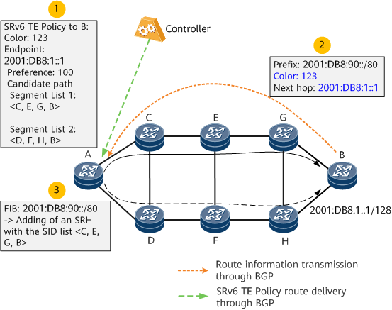
The process of color-based traffic steering is as follows:
Use a controller to deliver an SRv6 TE Policy to headend device A. The color value for the SRv6 TE Policy is 123 and the endpoint is 2001:DB8:1::1 (device B).
Configure a BGP or VPN export policy on device B (or a BGP or VPN import policy on device A), and set the color value to 123 for route prefix 2001:DB8:90::/80 and the next hop to 2001:DB8:1::1 (device B). Then, configure device B to send routing information to device A through a BGP peer relationship.
Configure a tunnel policy on device A. After receiving the BGP route 2001:DB8:90::/80, device A recurses the route to the SRv6 TE Policy based on the color value 123 and the next hop 2001:DB8:1::1. Before forwarding a packet destined for 2001:DB8:90::/80, device A adds a specific SID list <C, E, G, B> to the packet.
DSCP-based Traffic Steering
In DSCP-based traffic steering, the headend recurses traffic based on the next hop of the corresponding route in compliance with the configured tunnel policy. If traffic recursion to an SRv6 TE flow group is configured, the headend matches the traffic with an SRv6 mapping policy that has the same color value as the route. If such an SRv6 mapping policy exists, the headend dynamically generates an SRv6 TE flow group that contains multiple SRv6 TE Policies with the same endpoint but different color values.
If there is no such SRv6 mapping policy, the headend does not dynamically create an SRv6 TE flow group.
If multiple flows with the same color value but different next-hop addresses need to recurse to SRv6 TE flow groups, multiple dynamic SRv6 TE flow groups with different endpoints are created based on the configuration of the matching SRv6 mapping policy.
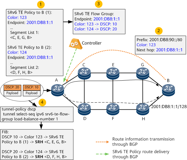
Figure 2 shows the DSCP-based traffic steering process.
- SRv6 TE Policy 1 and SRv6 TE Policy 2 are delivered to headend device A through a controller. The color values for SRv6 TE Policy 1 and SRv6 TE Policy 2 are 123 and 124, respectively. The endpoints of the policies are both 2001:DB8:1::1 (device B).
- Device B sends the BGP route 2001:DB8:90::/80 to device A through a BGP peer relationship.
- After a tunnel selection policy and an SRv6 mapping policy are configured on device A, the device dynamically generates an SRv6 TE flow group based on the configurations.
- On device A, services are associated with the SRv6 TE flow group based on the next hop of the involved service route, and carry DSCP information during forwarding. Based on the SRv6 mapping policy configuration, the services are first associated with a specific color and then a specific SRv6 TE Policy in the SRv6 TE flow group, thereby implementing DSCP-based traffic steering.
In an SRv6 mapping policy, you can configure a separate color-DSCP mapping rule for both the IPv4 address family traffic and IPv6 address family traffic. In the same address family (IPv4 or IPv6), each DSCP value can be mapped to only one color value. Furthermore, such a mapping rule can be configured for an SRv6 TE Policy only if this policy is up.
When IPv4/IPv6 packets with DSCP values enter an SRv6 TE flow group, they are matched against the following rules in sequence to achieve forwarding:
- The packets are first strictly matched against the SRv6 TE Policy-specific or native IP link-specific rule configured with specified DSCP values in the corresponding address family.
- If the matching fails, the packets are matched against the SRv6 TE Policy-specific or native IP link-specific rule configured with the default priority in the local address family.
- If the matching fails, the packets are matched against the SRv6 TE Policy-specific or native IP link-specific rule configured with the smallest DSCP value in the local address family.
- If the matching fails, the packets are matched against the SRv6 TE Policy-specific or native IP link-specific rule configured with the default priority in the other address family.
- If the matching fails, the packets are matched against the SRv6 TE Policy-specific or native IP link-specific rule configured with the smallest DSCP value in the other address family.
Service Class-based Traffic Steering
In service class-based traffic steering, the headend recurses traffic based on the next hop of the corresponding route in compliance with the configured tunnel policy. If traffic recursion to an SRv6 TE flow group is configured, the headend matches the traffic with an SRv6 mapping policy that has the same color value as the route. If such an SRv6 mapping policy exists, the headend dynamically generates an SRv6 TE flow group that contains multiple SRv6 TE Policies with the same endpoint but different color values.
If there is no such SRv6 mapping policy, the headend does not dynamically create an SRv6 TE flow group.
If multiple flows with the same color value but different next-hop addresses need to recurse to SRv6 TE flow groups, multiple dynamic SRv6 TE flow groups with different endpoints are created based on the configuration of the matching SRv6 mapping policy.
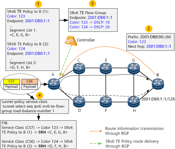
Figure 3 shows the service class-based traffic steering process.
- SRv6 TE Policy 1 and SRv6 TE Policy 2 are delivered to headend device A through a controller. The color values for SRv6 TE Policy 1 and SRv6 TE Policy 2 are 123 and 124, respectively. The endpoints of the policies are both 2001:DB8:1::1 (device B).
- Device B sends the BGP route 2001:DB8:90::/80 to device A through a BGP peer relationship.
- A tunnel selection policy and SRv6 mapping policy are configured on device A, the mapping type of the SRv6 mapping policy is set to Service Class, and a rule is defined either for the mapping between the color values of SRv6 TE Policies and the service class values of packets or for the mapping between native IP links and the service class values of packets. Based on these configurations, the device dynamically generates an SRv6 TE flow group for services.
- On device A, services are associated with the SRv6 TE flow group based on the next hop of the involved service route, and carry service class information during forwarding. Based on the SRv6 mapping policy configuration, the services are first associated with a specific color and then a specific SRv6 TE Policy in the SRv6 TE flow group, thereby implementing service class-based traffic steering.
In an SRv6 mapping policy, you can specify a rule for the mapping between the color values of SRv6 TE Policies and the service class values of packets or for the mapping between native IP links and the service class values of packets. Each service class value can be associated with only one SRv6 TE Policy or native IP link. Furthermore, such a mapping rule can be configured for an SRv6 TE Policy only if this policy is up.
When packets with service class values enter an SRv6 TE Policy group, they are matched against the following rules in sequence to achieve forwarding:
1. The packets are first strictly matched against the SRv6 TE Policy-specific or native IP link-specific rule configured with the corresponding service class value.
2. If the matching fails, the packets are matched against the SRv6 TE Policy-specific or native IP link-specific rule configured with the default priority.
3. If the rule configured with the default priority does not exist or it fails to go up, the packets are matched against the SRv6 mapping policy rule that is configured with the smallest index and remains up. As such, it is recommended that low-priority service classes (BE < AF1 < AF2 < AF3 < AF4 < EF < CS6 < CS7) be specified in the SRv6 mapping policy rule with a small index. This ensures that unmatched traffic preferentially preempts the low-priority bandwidth instead of the high-priority bandwidth.


