Configuring L3VPNv4 over SRv6 BE

This section describes how to configure L3VPNv4 over SRv6 BE.

Usage Scenario

L3VPNv4 over SRv6 BE allows SRv6 BE paths on public networks to carry L3VPNv4 data. The implementation of L3VPNv4 over SRv6 BE involves establishing SRv6 BE paths, advertising VPN routes, and forwarding data.

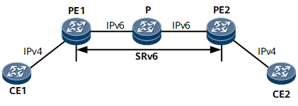
As shown in Figure 1, PE1 and PE2 communicate through an IPv6 public network. The VPN is a traditional IPv4 network. SRv6 BE paths can be deployed on the IPv6 public network to carry L3VPNv4 services on the VPN.

Figure 1 L3VPNv4 over SRv6 BE networking

Pre-configuration Tasks

Before configuring L3VPNv4 over SRv6 BE, complete the following tasks:

  • Configure a link layer protocol.

  • Configure network-layer addresses for interfaces to ensure that neighboring devices are reachable at the network layer.

Procedure

  1. Configure IPv6 IS-IS on each PE and P. For configuration details, see Configuring Basic IPv6 IS-IS Functions.
  2. Configure a VPN instance on each PE and enable the IPv4 address family for the instance.
    1. Run system-view

      The system view is displayed.

    2. Run ip vpn-instance vpn-instance-name

      A VPN instance is created, and its view is displayed.

    3. Run ipv4-family

      The VPN instance IPv4 address family is enabled, and its view is displayed.

    4. Run route-distinguisher route-distinguisher

      An RD is configured for the VPN instance IPv4 address family.

    5. Run vpn-target vpn-target &<1-8> [ both | export-extcommunity | import-extcommunity ]

      VPN targets are configured for the VPN instance IPv4 address family.

    6. Run commit

      The configuration is committed.

    7. Run quit

      Exit the VPN instance IPv4 address family view.

    8. Run quit

      Exit the VPN instance view.

    9. Run interface interface-type interface-number

      The view of the interface to be bound to the VPN instance is displayed.

    10. Run ip binding vpn-instance vpn-instance-name

      The VPN instance is bound to the interface.

      Running the ip binding vpn-instance command deletes Layer 3 (including IPv4 and IPv6) configurations, such as IP address and routing protocol configurations, on the involved interface. If needed, reconfigure them after running the command.

    11. Run ip address ip-address { mask | mask-length }

      An IP address is configured for the interface.

      Some Layer 3 functions, such as route exchange between the PE and CE, can be configured only after an IP address is configured for the VPN interface on the PE.

    12. Run commit

      The configuration is committed.

    13. Run quit

      Exit the interface view.

  3. Configure IPv4 route exchange between the PE and CE. For configuration details, see Configuring Route Exchange Between PEs and CEs.
  4. Establish an MP-IBGP peer relationship between the PEs.
    1. Run bgp { as-number-plain | as-number-dot }

      The BGP view is displayed.

    2. Run router-id ipv4-address

      A router ID is configured.

    3. Run peer ipv6-address as-number { as-number-plain | as-number-dot }

      The remote PE is configured as a peer.

    4. Run peer ipv6-address connect-interface loopback interface-number

      The interface on which a TCP connection to the specified BGP peer is established is specified.

    5. Run ipv4-family vpnv4

      The BGP VPNv4 address family view is displayed.

    6. Run peer ipv6-address enable

      The device is enabled to exchange VPN-IPv4 routes with the specified peer.

    7. Run commit

      The configuration is committed.

    8. Run quit

      Exit the BGP VPNv4 address family view.

    9. Run quit

      Exit the BGP view.

  5. Configure basic SRv6 functions.
    1. Run segment-routing ipv6

      SRv6 is enabled, and the SRv6 view is displayed.

    2. Run encapsulation source-address ipv6-address [ ip-ttl ttl-value ]

      A source address is specified for SRv6 VPN encapsulation.

    3. Run locator locator-name [ ipv6-prefix ipv6-address prefix-length [ static static-length | args args-length ] * ]

      An SRv6 locator is configured.

    4. (Optional) Run opcode func-opcode end-dt4 vpn-instance vpn-instance-name

      A static SID operation code (opcode) is configured.

      An End.DT4 SID can be either dynamically allocated through BGP or manually configured. If you want to enable dynamic End.DT4 SID allocation using the segment-routing ipv6 locator locator-name command, skip this step.

    5. Run quit

      Exit the SRv6 locator view.

    6. Run quit

      Exit the SRv6 view.

  6. Enable IS-IS SRv6 on PEs.
    1. Run isis [ process-id ]

      The IS-IS view is displayed.

    2. Run ipv6 enable topology ipv6

      The IPv6 capability is enabled for the IS-IS process in the IPv6 topology.

    3. Run segment-routing ipv6 locator locator-name [ auto-sid-disable ]

      IS-IS SRv6 is enabled.

    4. Run quit

      Exit the IS-IS view.

  7. Configure VPN routes on PEs to carry SIDs and recurse to SRv6 BE paths based on the SIDs.
    1. Run bgp { as-number-plain | as-number-dot }

      The BGP view is displayed.

    2. Run ipv4-family vpnv4

      The BGP VPNv4 address family view is displayed.

    3. Run peer ipv6-address prefix-sid [ sid-type5 | advertise-srv6-locator ]

      The device is enabled to exchange IPv4 prefix SIDs with the specified IPv6 peer.

      In a scenario where BFD is used to check locator reachability and the P nodes between local and remote PEs summarize locator routes, you can specify the advertise-srv6-locator parameter to enable PE-advertised BGP routes to carry locator length information. In this way, when the peer IPv6 address bound to the BFD session matches the locator's IPv6 address, locator reachability can be checked using BFD to complete VPN FRR or auto FRR path switching.

    4. Run quit

      Exit the BGP VPNv4 address family view.

    5. Run ipv4-family vpn-instance vpn-instance-name

      The BGP-VPN instance IPv4 address family view is displayed.

    6. Run segment-routing ipv6 best-effort

      The device is enabled to perform private network route recursion based on the SIDs carried by routes.

    7. Run segment-routing ipv6 locator locator-name [ auto-sid-disable ]

      The device is enabled to add SIDs to VPN routes.

      If auto-sid-disable is not specified, dynamic SID allocation is supported. If there are static SIDs in the range of the locator specified using locator-name, the static SIDs are used. Otherwise, dynamically allocated SIDs are used.

      If auto-sid-disable is specified, BGP does not dynamically allocate SIDs.

    8. Run commit

      The configuration is committed.

Verifying the Configuration

After configuring L3VPNv4 over SRv6 BE, verify the configuration.

  • Run the display segment-routing ipv6 locator [ locator-name ] verbose command to check SRv6 locator information.

  • Run the display segment-routing ipv6 local-sid { end | end-x | end-dt4 } [ sid ] forwarding command to check information about the SRv6 local SID table.

  • Run the display bgp vpnv4 { all | route-distinguisher route-distinguisher | vpn-instance vpn-instance-name } routing-table [ network [ prefix-length ] ] command to check BGP VPNv4 route information.

  • Run the ping command to check the connectivity between CEs.

Copyright © Huawei Technologies Co., Ltd.
Next topic >