This section describes how to configure EVPN VPWS over SRv6 BE.
Usage Scenario
EVPN VPWS over SRv6 BE uses public SRv6 BE to carry EVPN services. The implementation of EVPN VPWS over SRv6 BE involves establishing SRv6 BE paths, advertising EVPN routes, and forwarding data.
As shown in Figure 1, PE1 and PE2 communicate through an IPv6 public network. SRv6 BE is deployed on the public IPv6 network to carry Layer 2 EVPN services.
Figure 1 EVPN VPWS over SRv6 BE networking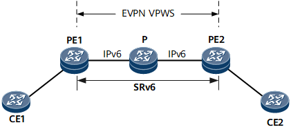
Pre-configuration Tasks
Before configuring EVPN VPWS over SRv6 BE, complete the following tasks:
Procedure
- Configure IPv6 IS-IS on each PE and P. For details, see Configuring Basic IPv6 IS-IS Functions.
- Configure EVPN and EVPL instances on each PE.
- Run system-view
The system view is displayed.
- Run evpn source-address ip-address
An EVPN source address is configured.
In scenarios where a CE is dual-homed or multi-homed to PEs, you need to configure an EVPN source address on each PE to generate route distinguishers (RDs) for Ethernet segment routes and Ethernet auto-discovery per ES routes.
- Run evpn vpn-instance vpn-instance-name vpws
An EVPN instance that works in VPWS mode is created.
- Run route-distinguisher route-distinguisher
An RD is configured for the EVPN instance.
An EVPN instance takes effect only after an RD is configured for it. The RDs of different EVPN instances on a PE must be different.

After being configured, an RD cannot be modified but can be deleted. If the RD of an EVPN instance is deleted, VPN targets configured for the EVPN instance are also deleted.
- Run vpn-target vpn-target &<1-8> [ both | export-extcommunity | import-extcommunity ]
VPN targets are configured for the EVPN instance.
VPN targets are BGP extended community attributes used to control the receiving and advertisement of EVPN routes. A maximum of eight VPN targets can be configured using the vpn-target command. To configure more VPN targets for an EVPN instance address family, run the vpn-target command multiple times.
An RT of an Ethernet segment route is generated using the middle six bytes of an ESI. For example, if the ESI is 0011.1001.1001.1001.1002, the Ethernet segment route uses 11.1001.1001.10 as its RT.
- Run quit
Return to the system view.
- Run evpl instance evpl-id
An EVPL instance is created.
- Run evpn binding vpn-instance vpn-instance-name
A specified EVPN instance that works in VPWS mode is bound to the current EVPL instance.
- Run local-service-id service-id remote-service-id service-id
The packets of the current EVPL instance are configured to carry the local and remote service IDs.
- (Optional) Run mtu-match ignore
The MTU matching check is ignored for the EVPL instance. In scenarios where a Huawei device interworks with a non-Huawei device through an EVPN VPWS, if the non-Huawei device does not support any MTU matching check for an EVPL instance, run the mtu-match ignore command to ignore the MTU matching check.
- (Optional) Run load-balancing ignore-esi
The device is disabled from checking ESI validity during EVPL instance load balancing.
In an EVPN VPWS scenario where active-active protection is deployed, if each access-side device is single-homed to an aggregation-side device and no ESI is configured on the access interface, to implement active-active load balancing, you can run this command on the aggregation-side device to enable the device to ignore ESI validity check during EVPL instance load balancing.
- Run quit
Return to the system view.
- Configure an AC interface.
- Run interface interface-type interface-number.subnum mode l2
A Layer 2 sub-interface is created and its view is displayed.
Before running this command, ensure that the Layer 2 interface on which a Layer 2 sub-interface is to be created does not have the port link-type dot1q-tunnel command configuration. If this configuration exists, run the undo port link-type command to delete the configuration.
In addition to a Layer 2 sub-interface, an Ethernet main interface, Layer 3 sub-interface, or Eth-Trunk interface can also function as an AC interface.
- Run encapsulation { dot1q [ vid low-pe-vid [ to high-pe-vid ] ] | untag | qinq [ vid pe-vid ce-vid { low-ce-vid [ to high-ce-vid ] | default } ] }
An encapsulation type of packets allowed to pass through the Layer 2 sub-interface is configured.
- Run evpl instance evpl-id
A specified EVPL instance is bound to the Layer 2 sub-interface.
- (Optional) Run evpn-vpws ignore-ac-state
The interface is enabled to ignore the AC status.
On a network with primary and backup links, if CFM is associated with an AC interface, run this command to ensure EVPN VPWS continuity. When the AC status of the interface becomes down, a primary/backup link switchover is triggered. As the interface has been enabled to ignore the AC status using this command, the EVPN VPWS does not need to be re-established during the link switchover.
- Run quit
Exit the Layer 2 sub-interface view.
- Establish a BGP EVPN peer relationship between PEs.
- Run bgp { as-number-plain | as-number-dot }
The BGP view is displayed.
- Run router-id ipv4-address
A BGP router ID is configured.
- Run peer ipv6-address as-number { as-number-plain | as-number-dot }
The remote PE is configured as a peer.
- Run peer ipv6-address connect-interface loopback interface-number
The interface used to set up a TCP connection with the specified BGP peer is specified.
- Run l2vpn-family evpn
The BGP EVPN address family view is displayed.
- Run peer ipv6-address enable
The device is enabled to exchange EVPN routes with the specified peer.
- Run quit
Exit the BGP EVPN address family view.
- Run quit
Exit the BGP view.
- Run commit
The configuration is committed.
- Configure basic SRv6 functions.
- (Optional) Run evpn srv6 next-header-field { 59 | 143 }
A value is set for the Next Header field in an SRv6 extension header.
If the value is 59 in earlier versions, you can perform this step to change the value to 59 to ensure compatibility with the earlier versions.
- Run segment-routing ipv6
SRv6 is enabled, and the SRv6 view is displayed.
- Run encapsulation source-address ipv6-address [ ip-ttl ttl-value ]
A source address is specified for SRv6 EVPN encapsulation.
- Run locator locator-name [ ipv6-prefix ipv6-address prefix-length [ static static-length | args args-length ] * ]
An SRv6 locator is configured.
- (Optional) Run opcode func-opcode end-dx2 evpl-instance evpl-instance-id
A static SID opcode is configured.
An End.DX2 SID can be either dynamically allocated through BGP or manually configured. If you want to run the segment-routing ipv6 locator locator-name command to enable dynamic End.DX2 SID allocation through BGP, you can skip this step.
- (Optional) Run opcode func-opcode end-dx2l evpl-instance evpl-instance-id
An End.DX2L SID opcode is configured. You can run this command to manually specify a SID for a bypass path.
- Run quit
Exit the SRv6 locator view.
- Run quit
Exit the SRv6 view.
- Enable IS-IS SRv6.
- Run isis [ process-id ]
The IS-IS view is displayed.
- Run ipv6 enable topology ipv6
The IPv6 capability is enabled for the IS-IS process in the IPv6 topology.
- Run segment-routing ipv6 locator locator-name [ auto-sid-disable ]
IS-IS SRv6 is enabled.
In this command, the value of locator-name must be the same as that configured using locator locator-name [ ipv6-prefix ipv6-address prefix-length [ static static-length | args args-length ] * ].
- Run quit
Exit the IS-IS view.
- Configure EVPN routes on PEs to carry SIDs and recurse to SRv6 BE paths based on the SIDs.
- Run bgp { as-number-plain | as-number-dot }
The BGP view is displayed.
- Run l2vpn-family evpn
The BGP EVPN address family view is displayed.
- Run peer { ipv6-address | group-name } advertise encap-type srv6 [ advertise-srv6-locator ]
The device is enabled to send EVPN routes carrying SRv6-encapsulated attributes to the specified peer or peer group.
In a scenario where BFD is used to check locator reachability, after locator routes are summarized by a P device between local and remote PEs, the remote PE can learn only the summary locator route, not the locator on the local PE. This leads to a BFD failure. To address this issue, configure the advertise-srv6-locator parameter in the command to allow the local PE to carry locator length information in the EVPN route advertised to the remote PE. In this way, after receiving the EVPN route, the remote PE can calculate the locator on the local PE, enabling BFD to take effect.
- Run quit
Exit the BGP EVPN address family view.
- Run quit
Exit the BGP view.
- Run evpl instance evpl-id
The view of an EVPL instance is displayed.
- Run segment-routing ipv6 locator locator-name
The device is enabled to add SIDs to EVPN routes to be sent.
If there are static SIDs in the range of the locator specified using locator-name, use the static SIDs. Otherwise, use dynamically allocated SIDs.
- Run quit
Exit the view of the EVPL instance.
- Run evpn vpn-instance vpn-instance-name vpws
The view of the EVPN instance that works in VPWS mode is displayed.
- Run segment-routing ipv6 best-effort
The device is enabled to perform route recursion to SRv6 BE paths based on the SIDs carried by routes.
- Run quit
Return to the system view.
- Run commit
The configuration is committed.
- (Optional) Verify EVPN VPWS connectivity.
- Configure an End.OP SID on the remote PE.
- Run segment-routing ipv6
The SRv6 view is displayed.
- Run locator locator-name
The locator view is displayed.
- Run opcode func-opcode end-op
An End.OP SID opcode is configured.
- Run commit
The configuration is committed.
- Perform the following steps on the local PE:
- Run segment-routing ipv6
The SRv6 view is displayed.
- Run remote end-op op-sid prefix-length
A remote End.OP SID is configured.
- Run commit
The configuration is committed.
- Perform the following steps on the local PE:
Verifying the Configuration
After configuring EVPN VPWS over SRv6 BE, verify the configuration.
Run the display bgp evpn evpl command to check all EVPL instance information.
Run the display bgp evpn { all | route-distinguisher route-distinguisher | vpn-instance vpn-instance-name } routing-table [ { ad-route | es-route | inclusive-route | mac-route | prefix-route } prefix ] command to check BGP EVPN route information.
Run the display segment-routing ipv6 local-sid end-dx2 evpl-instance evpl-id forwarding command to check information about the SRv6 BE local SID table.