Example for Configuring Static VPWS Accessing VPLS
This section provides an example for configuring static VPWS accessing VPLS on an HVPLS network where UPEs do not support VPLS.
Networking Requirements
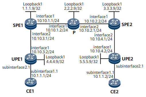
On the network shown in Figure 1, UPEs do not support VPLS, but CE1 and CE2 need to communicate. To meet this requirement, configure SVC VPWS on UPEs and static VPLS on SPEs.

Configuration Roadmap
The configuration roadmap is as follows:
Configure SVC VPWS on UPEs.
Configure static VPLS on SPEs.
Enable MAC Withdraw for the VSI on each SPE.
Data Preparation
To complete the configuration, you need the following data:
VSI name and VSI ID
MPLS LSR IDs of UPEs and SPEs, which are used as peer IP addresses
Routing protocol
Procedure
- Configure interface IP addresses for CEs, UPEs, and SPEs in accordance with Configuration Files.
- Configure an IGP (OSPF in this example) on the MPLS backbone network.
# Configure SPE1.
<SPE1> system-view
[~SPE1] ospf
[*SPE1-ospf-1] area 0
[*SPE1-ospf-1-area-0.0.0.0] network 1.1.1.9 0.0.0.0
[*SPE1-ospf-1-area-0.0.0.0] network 10.10.1.0 0.0.0.255
[*SPE1-ospf-1-area-0.0.0.0] network 10.10.3.0 0.0.0.255
[*SPE1-ospf-1-area-0.0.0.0] quit
[*SPE1-ospf-1] quit
[*SPE1] commit
# Configure the P.
<P> system-view
[~P] ospf
[*P-ospf-1] area 0
[*P-ospf-1-area-0.0.0.0] network 2.2.2.9 0.0.0.0
[*P-ospf-1-area-0.0.0.0] network 10.10.1.0 0.0.0.255
[*P-ospf-1-area-0.0.0.0] network 10.10.2.0 0.0.0.255
[*P-ospf-1-area-0.0.0.0] quit
[*P-ospf-1] quit
[*P] commit
# Configure SPE2.
<SPE2> system-view
[~SPE2] ospf
[*SPE2-ospf-1] area 0
[*SPE2-ospf-1-area-0.0.0.0] network 3.3.3.9 0.0.0.0
[*SPE2-ospf-1-area-0.0.0.0] network 10.10.2.0 0.0.0.255
[*SPE2-ospf-1-area-0.0.0.0] network 10.10.4.0 0.0.0.255
[*SPE2-ospf-1-area-0.0.0.0] quit
[*SPE2-ospf-1] quit
[*SPE2] commit
# Configure UPE1.
<UPE1> system-view
[~UPE1] ospf
[*UPE1-ospf-1] area 0
[*UPE1-ospf-1-area-0.0.0.0] network 4.4.4.9 0.0.0.0
[*UPE1-ospf-1-area-0.0.0.0] network 10.10.3.0 0.0.0.255
[*UPE1-ospf-1-area-0.0.0.0] quit
[*UPE1-ospf-1] quit
[*UPE1] commit
# Configure UPE2.
<UPE2> system-view
[~UPE2] ospf
[*UPE2-ospf-1] area 0
[*UPE2-ospf-1-area-0.0.0.0] network 5.5.5.9 0.0.0.0
[*UPE2-ospf-1-area-0.0.0.0] network 10.10.4.0 0.0.0.255
[*UPE2-ospf-1-area-0.0.0.0] quit
[*UPE2-ospf-1] quit
[*UPE2] commit
After completing the configurations, check OSPF route information. The following example uses the command output on SPE1.
<SPE1> display ospf routing OSPF Process 1 with Router ID 10.10.3.1 Routing Tables Routing for Network Destination Cost Type NextHop AdvRouter Area 1.1.1.9/32 0 Direct 1.1.1.9 10.10.3.1 0.0.0.0 2.2.2.9/32 1 Stub 10.10.1.2 10.10.1.2 0.0.0.0 3.3.3.9/32 2 Stub 10.10.1.2 10.10.2.2 0.0.0.0 4.4.4.9/32 1 Stub 10.10.3.2 10.10.3.2 0.0.0.0 5.5.5.9/32 3 Stub 10.10.1.2 10.10.4.2 0.0.0.0 10.10.1.0/24 1 Direct 10.10.1.1 10.10.3.1 0.0.0.0 10.10.2.0/24 2 Transit 10.10.1.2 10.10.1.2 0.0.0.0 10.10.3.0/24 1 Direct 10.10.3.1 10.10.3.1 0.0.0.0 10.10.4.0/24 3 Transit 10.10.1.2 10.10.2.2 0.0.0.0 Total Nets: 9 Intra Area: 9 Inter Area: 0 ASE: 0 NSSA: 0 - Configure basic MPLS functions on the MPLS backbone network.
# Configure SPE1.
[~SPE1] mpls lsr-id 1.1.1.9
[*SPE1] mpls
[*SPE1-mpls] quit
[*SPE1] mpls ldp
[*SPE1-mpls-ldp] quit
[*SPE1] interface gigabitethernet 0/1/0
[*SPE1-GigabitEthernet0/1/0] mpls
[*SPE1-GigabitEthernet0/1/0] mpls ldp
[*SPE1-GigabitEthernet0/1/0] quit
[*SPE1] interface gigabitethernet 0/1/8
[*SPE1-GigabitEthernet0/1/8] mpls
[*SPE1-GigabitEthernet0/1/8] mpls ldp
[*SPE1-GigabitEthernet0/1/8] quit
[*SPE1] commit
# Configure the P.
[~P] mpls lsr-id 2.2.2.9
[*P] mpls
[*P-mpls] quit
[*P] mpls ldp
[*P-mpls-ldp] quit
[*P] interface gigabitethernet 0/1/0
[*P-GigabitEthernet0/1/0] mpls
[*P-GigabitEthernet0/1/0] mpls ldp
[*P-GigabitEthernet0/1/0] quit
[*P] interface gigabitethernet 0/1/8
[*P-GigabitEthernet0/1/8] mpls
[*P-GigabitEthernet0/1/8] mpls ldp
[*P-GigabitEthernet0/1/8] quit
[*P] commit
# Configure SPE2.
[~SPE2] mpls lsr-id 3.3.3.9
[*SPE2] mpls
[*SPE2-mpls] quit
[*SPE2] mpls ldp
[*SPE2-mpls-ldp] quit
[*SPE2] interface gigabitethernet 0/1/0
[*SPE2-GigabitEthernet0/1/0] mpls
[*SPE2-GigabitEthernet0/1/0] mpls ldp
[*SPE2-GigabitEthernet0/1/0] quit
[*SPE2] interface gigabitethernet 0/1/8
[*SPE2-GigabitEthernet0/1/8] mpls
[*SPE2-GigabitEthernet0/1/8] mpls ldp
[*SPE2-GigabitEthernet0/1/8] quit
[*SPE2] commit
# Configure UPE1.
[~UPE1] mpls lsr-id 4.4.4.9
[*UPE1] mpls
[*UPE1-mpls] quit
[*UPE1] mpls ldp
[*UPE1-mpls-ldp] quit
[*UPE1] interface gigabitethernet 0/1/0
[*UPE1-GigabitEthernet0/1/0] mpls
[*UPE1-GigabitEthernet0/1/0] mpls ldp
[*UPE1-GigabitEthernet0/1/0] quit
[*UPE1] commit
# Configure UPE2.
[~UPE2] mpls lsr-id 5.5.5.9
[*UPE2] mpls
[*UPE2-mpls] quit
[*UPE2] mpls ldp
[*UPE2-mpls-ldp] quit
[*UPE2] interface gigabitethernet 0/1/0
[*UPE2-GigabitEthernet0/1/0] mpls
[*UPE2-GigabitEthernet0/1/0] mpls ldp
[*UPE2-GigabitEthernet0/1/0] quit
[~UPE2] commit
After completing the configurations, run the display mpls ldp session command on SPEs and the P. The command output shows that Status of the peer relationships between SPE1 and the P and between SPE2 and the P is Operational. Run the display mpls lsp command. The command output shows the LSP status.
The following example uses the command output on SPE1.
<SPE1> display mpls ldp session LDP Session(s) in Public Network Codes: LAM(Label Advertisement Mode), SsnAge Unit(DDDD:HH:MM) An asterisk (*) before a session means the session is being deleted. -------------------------------------------------------------------------- PeerID Status LAM SsnRole SsnAge KASent/Rcv -------------------------------------------------------------------------- 2.2.2.9:0 Operational DU Passive 0000:00:38 154/154 4.4.4.9:0 Operational DU Passive 0000:00:16 69/69 -------------------------------------------------------------------------- TOTAL: 2 Session(s) Found. <SPE1> display mpls lsp Flag after Out IF: (I) - RLFA Iterated LSP, (I*) - Normal and RLFA Iterated LSP Flag after LDP FRR: (L) - Logic FRR LSP ------------------------------------------------------------------------------- LSP Information: LDP LSP ------------------------------------------------------------------------------- FEC In/Out Label In/Out IF Vrf Name 1.1.1.9/32 3/NULL -/- 2.2.2.9/32 NULL/3 -/GE0/1/0 2.2.2.9/32 32828/3 -/GE0/1/0 3.3.3.9/32 NULL/32829 -/GE0/1/0 3.3.3.9/32 32829/32829 -/GE0/1/0 4.4.4.9/32 NULL/3 -/GE0/1/8 4.4.4.9/32 32830/3 -/GE0/1/8 5.5.5.9/32 NULL/32831 -/GE0/1/0 5.5.5.9/32 32831/32831 -/GE0/1/0 - Configure VPWS on each UPE.
# Configure UPE1.
<UPE1> system-view
[~UPE1] mpls l2vpn
[*UPE1-l2vpn] quit
[*UPE1] interface gigabitethernet 0/1/8.1
[*UPE1-GigabitEthernet0/1/8.1] vlan-type dot1q 1
[*UPE1-GigabitEthernet0/1/8.1] mpls static-l2vc destination 1.1.1.9 transmit-vpn-label 100 receive-vpn-label 200
[*UPE1-GigabitEthernet0/1/8.1] quit
[*UPE1] commit
# Configure UPE2.
<UPE2> system-view
[~UPE2] mpls l2vpn
[*UPE2-l2vpn] quit
[*UPE2] interface gigabitethernet 0/1/8.1
[*UPE2-GigabitEthernet0/1/8.1] vlan-type dot1q 1
[*UPE2-GigabitEthernet0/1/8.1] mpls static-l2vc destination 3.3.3.9 transmit-vpn-label 100 receive-vpn-label 200
[*UPE2-GigabitEthernet0/1/8.1] quit
[*UPE2] commit
- # Configure VPLS on each SPE.
# Configure SPE1.
<SPE1> system-view
[~SPE1] mpls l2vpn
[*SPE1-l2vpn] quit
[*SPE1] vsi v100
[*SPE1-vsi-v100] pwsignal ldp
[*SPE1-vsi-v100-ldp] vsi-id 100
[*SPE1-vsi-v100-ldp] mac-withdraw enable
[*SPE1-vsi-v100-ldp] peer 3.3.3.9 static-npe trans 300 recv 400
[*SPE1-vsi-v100-ldp] peer 4.4.4.9 static-upe trans 200 recv 100
[*SPE1-vsi-v100-ldp] quit
[*SPE1-vsi-v100] quit
[*SPE1] commit
# Configure SPE2.
<SPE2> system-view
[~SPE2] mpls l2vpn
[*SPE2-l2vpn] quit
[*SPE2] vsi v100
[*SPE2-vsi-v100] pwsignal ldp
[*SPE2-vsi-v100-ldp] vsi-id 100
[*SPE2-vsi-v100-ldp] mac-withdraw enable
[*SPE2-vsi-v100-ldp] peer 1.1.1.9 static-npe trans 400 recv 300
[*SPE2-vsi-v100-ldp] peer 5.5.5.9 static-upe trans 200 recv 100
[*SPE2-vsi-v100-ldp] quit
[*SPE2-vsi-v100] quit
[*SPE2] commit
- Verify the configuration.
After completing the configurations, run the display mpls static-l2vc command on a UPE. The command output shows that a PW has been established and VC State is up. The following example uses the command output on UPE1.
<UPE1> display mpls static-l2vc
 Total svc connections:  1,  1 up,  0 down

 *Client Interface     : GigabitEthernet0/1/0.1 is up
  AC Status            : up
  VC State           : up
  VC ID                : 0
  VC Type              : VLAN
  Destination          : 1.1.1.9
  Transmit VC Label    : 100
  Receive VC Label     : 200
  Label Status         : 0
  Token Status         : 0
  Control Word         : Disable
  VCCV Capability      : alert ttl lsp-ping bfd
  active state         : active
  OAM Protocol         : --
  OAM Status           : --
  OAM Fault Type       : --
  PW APS ID            : --
  PW APS Status        : --
  TTL Value            : 1
  Link State           : up
  Tunnel Policy Name   : --
  PW Template Name     : --
  Main or Secondary    : Main
  load balance type    : flow
  Access-port          : false
  VC tunnel/token info : 1 tunnels/tokens
  NO.0  TNL Type       : ldp   , TNL ID : 0x0000000001004c4b42
  Create time          : 0 days, 0 hours, 11 minutes, 21 seconds
  UP time              : 0 days, 0 hours, 1 minutes, 29 seconds
  Last change time     : 0 days, 0 hours, 1 minutes, 29 seconds
  VC last up time      : 2015/05/30 17:34:22
  VC total up time     : 0 days, 0 hours, 1 minutes, 29 seconds
  CKey                 : 33
  NKey                 : 2818572439
Run the display vsi name v100 verbose command on an SPE. The command output shows that the VSI named v100 is Up and the corresponding PW is also Up. The following example uses the command output on SPE1.
<SPE1> display vsi name v100 verbose
 ***VSI Name               : v100
    Work Mode              : normal
    Administrator VSI      : no
    Isolate Spoken         : disable
    VSI Index              : 1
    PW Signaling           : ldp
    Member Discovery Style : --
    Bridge-domain Mode     : disable
    PW MAC Learn Style     : unqualify
    Encapsulation Type     : vlan
    MTU                    : 1500
    Diffserv Mode          : uniform
    Service Class          : --
    Color                  : --
    DomainId               : 255
    Domain Name            :
    Ignore AcState         : disable
    P2P VSI                : disable
    Create Time            : 0 days, 0 hours, 9 minutes, 44 seconds
    VSI State            : up
    Resource Status        : --

    VSI ID                 : 100
    LDP MAC-WITHDRAW       : mac-withdraw Enable
   *Peer Router ID         : 3.3.3.9
    primary or secondary   : primary
    ignore-standby-state   : no
    VC Label               : 400
    Peer Type              : static
    Tunnel ID              : 0x0000000001004c4b43
    Broadcast Tunnel ID    : --
    Broad BackupTunnel ID  : --
    CKey                   : 1
    NKey                   : 1358954644
    Stp Enable             : 0
    PwIndex                : 1
    Control Word           : disable
   *Peer Router ID         : 4.4.4.9
    primary or secondary   : primary
    ignore-standby-state   : no
    VC Label               : 100
    Peer Type              : static
    Tunnel ID              : 0x0000000001004c4b44
    Broadcast Tunnel ID    : --
    Broad BackupTunnel ID  : --
    CKey                   : 2
    NKey                   : 1358954645
    Stp Enable             : 0
    PwIndex                : 2
    Control Word           : disable

  **PW Information:

   *Peer Ip Address        : 3.3.3.9
    PW State             : up
    Local VC Label         : 400
    Remote VC Label        : 300
    Remote Control Word    : disable
    PW Type                : label
    Tunnel ID              : 0x0000000001004c4b43
    Broadcast Tunnel ID    : --
    Broad BackupTunnel ID  : --
    Ckey                   : 1
    Nkey                   : 1358954644
    Main PW Token          : 0x0
    Slave PW Token         : 0x0
    Tnl Type               : ldp
    OutInterface           :
    Backup OutInterface    : --
    Stp Enable             : 0
    Mac Flapping           : 0
    PW Last Up Time        : 2015/05/30 17:29:56
    PW Total Up Time       : 0 days, 0 hours, 9 minutes, 42 seconds
   *Peer Ip Address        : 4.4.4.9
    PW State               : up
    Local VC Label         : 100
    Remote VC Label        : 200
    Remote Control Word    : disable
    PW Type                : MEHVPLS
    Tunnel ID              : 0x0000000001004c4b44
    Broadcast Tunnel ID    : --
    Broad BackupTunnel ID  : --
    Ckey                   : 2
    Nkey                   : 1358954645
    Main PW Token          : 0x0
    Slave PW Token         : 0x0
    Tnl Type               : ldp
    OutInterface           :
    Backup OutInterface    : --
    Stp Enable             : 0
    Mac Flapping           : 0
    PW Last Up Time        : 2015/05/30 17:34:22
    PW Total Up Time       : 0 days, 0 hours, 3 minutes, 26 seconds
Configuration Files
CE1 configuration file
#
sysname CE1
#
interface GigabitEthernet0/1/0
 undo shutdown
#
interface GigabitEthernet0/1/0.1
 undo shutdown
 vlan-type dot1q 1
 ip address 10.1.1.1 255.255.255.0
#
return
CE2 configuration file
#
sysname CE2
#
interface GigabitEthernet0/1/0
 undo shutdown
#
interface GigabitEthernet0/1/0.1
 undo shutdown
 vlan-type dot1q 1
 ip address 10.1.1.2 255.255.255.0
#
return
UPE1 configuration file
#
sysname UPE1
#
mpls lsr-id 4.4.4.9
#
mpls
#
mpls l2vpn
#
mpls ldp
#
interface GigabitEthernet0/1/0
 undo shutdown
 ip address 10.10.3.2 255.255.255.0
 mpls
 mpls ldp
#
interface GigabitEthernet0/1/8
 undo shutdown
#
interface GigabitEthernet0/1/8.1
 vlan-type dot1q 1
 mpls static-l2vc destination 1.1.1.9 transmit-vpn-label 100 receive-vpn-label 200
#
interface LoopBack1
 ip address 4.4.4.9 255.255.255.255
#
ospf 1
 area 0.0.0.0
  network 4.4.4.9 0.0.0.0
  network 10.10.3.0 0.0.0.255
#
return
SPE1 configuration file
#
sysname SPE1
#
mpls lsr-id 1.1.1.9
#
mpls
#
mpls l2vpn
#
vsi v100
 pwsignal ldp
  vsi-id 100
  mac-withdraw enable
  peer 3.3.3.9 static-npe trans 300 recv 400
  peer 4.4.4.9 static-upe trans 200 recv 100
#
mpls ldp
#
interface GigabitEthernet0/1/0
 undo shutdown
 ip address 10.10.1.1 255.255.255.0
 mpls
 mpls ldp
#
interface GigabitEthernet0/1/8
 undo shutdown
 ip address 10.10.3.1 255.255.255.0
 mpls
 mpls ldp
#
interface LoopBack1
 ip address 1.1.1.9 255.255.255.255
#
ospf 1
 area 0.0.0.0
  network 1.1.1.9 0.0.0.0
  network 10.10.1.0 0.0.0.255
  network 10.10.3.0 0.0.0.255
#
return
P configuration file
#
sysname P
#
mpls lsr-id 2.2.2.9
#
mpls
#
mpls ldp
#
interface GigabitEthernet0/1/0
 undo shutdown
 ip address 10.10.1.2 255.255.255.0
 mpls
 mpls ldp
#
interface GigabitEthernet0/1/8
 undo shutdown
 ip address 10.10.2.1 255.255.255.0
 mpls
 mpls ldp
#
interface LoopBack1
 ip address 2.2.2.9 255.255.255.255
#
ospf 1
 area 0.0.0.0
  network 2.2.2.9 0.0.0.0
  network 10.10.1.0 0.0.0.255
  network 10.10.2.0 0.0.0.255
#
return
SPE2 configuration file
#
sysname SPE2
#
mpls lsr-id 3.3.3.9
#
mpls
#
mpls l2vpn
#
vsi v100
 pwsignal ldp
  vsi-id 100
  mac-withdraw enable
  peer 1.1.1.9 static-npe trans 400 recv 300
  peer 5.5.5.9 static-upe trans 200 recv 100
#
mpls ldp
#
interface GigabitEthernet0/1/0
 undo shutdown
 ip address 10.10.2.2 255.255.255.0
 mpls
 mpls ldp
#
interface GigabitEthernet0/1/8
 undo shutdown
 ip address 10.10.4.1 255.255.255.0
 mpls
 mpls ldp
#
interface LoopBack1
 ip address 3.3.3.9 255.255.255.255
#
ospf 1
 area 0.0.0.0
  network 3.3.3.9 0.0.0.0
  network 10.10.2.0 0.0.0.255
  network 10.10.4.0 0.0.0.255
#
return
UPE2 configuration file
#
sysname UPE2
#
mpls lsr-id 5.5.5.9
#
mpls
#
mpls l2vpn
#
mpls ldp
#
interface GigabitEthernet0/1/0
 undo shutdown
 ip address 10.10.4.2 255.255.255.0
 mpls
 mpls ldp
#
interface GigabitEthernet0/1/8
 undo shutdown
#
interface GigabitEthernet0/1/8.1
 vlan-type dot1q 1
 mpls static-l2vc destination 3.3.3.9 transmit-vpn-label 100 receive-vpn-label 200
#
interface LoopBack1
 ip address 5.5.5.9 255.255.255.255
#
ospf 1
 area 0.0.0.0
  network 5.5.5.9 0.0.0.0
  network 10.10.4.0 0.0.0.255
#
return