Example for Configuring VPLS PW Redundancy in an HVPLS Scenario
This section provides an example for configuring VPLS PW redundancy in an HVPLS scenario.
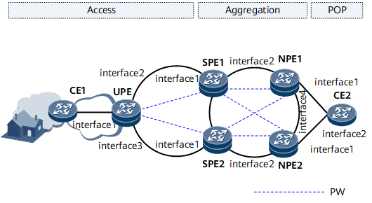
Networking Requirements
As shown in Figure 1, access and aggregation rings are deployed on the MAN. End-to-end LDP LSPs are deployed between PEs. An HVPLS network is established among the UPE, SPEs, and NPEs to carry multicast services, such as IPTV, on the MAN. Upstream traffic on the MAN is aggregated on the NPEs for transmission to the egress. CE2 is deployed at the egress of the MAN to assign IP addresses to users and provide IPTV services.
The service provider requires that multicast services be reliably transmitted even if an NPE or a PW fails, or an AC of CE2 fails. The service provider also requires that the deployed features be not vendor-specific and consume as less bandwidth as possible.
To meet the preceding requirements, configure VPLS PW redundancy in the HVPLS scenario. Connect the UPE to SPE1 and SPE2 using two PWs and configure the two PWs to work in backup mode. Connect the SPEs and NPEs using hub PWs. Configure an Eth-Trunk between CE2 and NPE1 and between CE2 and NPE2. Configure an E-Trunk between the NPEs and add the two Eth-Trunks to the E-Trunk. This configuration enhances network reliability with non-vendor-specific features. Meanwhile, the HVPLS networking reduces required PWs and bandwidth.

Interfaces 1 through 4 in this example represent GE 0/1/0, GE 0/1/1, GE 0/1/2, and GE 0/1/3, respectively.
Device |
Interface |
IP Address |
|---|---|---|
UPE |
GE 0/1/0 |
- |
GE 0/1/1 |
192.168.10.1/24 |
|
GE 0/1/2 |
192.168.20.1/24 |
|
Loopback 1 |
1.1.1.1/32 |
|
SPE1 |
GE 0/1/0 |
192.168.10.2/24 |
GE 0/1/1 |
192.168.30.1/24 |
|
Loopback 1 |
2.2.2.2/32 |
|
SPE2 |
GE 0/1/0 |
192.168.20.2/24 |
GE 0/1/1 |
192.168.50.1/24 |
|
Loopback 1 |
3.3.3.3/32 |
|
NPE1 |
GE 0/1/0 |
- |
GE 0/1/1 |
192.168.30.2/24 |
|
GE 0/1/3 |
192.168.60.1/24 |
|
Loopback 1 |
4.4.4.4/32 |
|
NPE2 |
GE 0/1/0 |
- |
GE 0/1/1 |
192.168.50.2/24 |
|
GE 0/1/3 |
192.168.60.2/24 |
|
Loopback 1 |
5.5.5.5/32 |
|
CE1 |
GE 0/1/0.10 |
10.1.1.1/24 |
CE2 |
GE 0/1/0 |
- |
GE 0/1/1 |
- |
|
VLANIF 10 |
10.1.1.2/24 |
Configuration Roadmap
The configuration roadmap is as follows:
- Configure an IP address and a routing protocol for each interface so that all PEs can communicate at the network layer. This example uses OSPF as the routing protocol.
Configure MPLS and public network tunnels.
In this example, LDP LSPs are used as tunnels between PEs.
- Enable MPLS and MPLS LDP globally on each PE.
- Enable MPLS on each PE interface.
- Enable MPLS LDP on the ingress and egress PE interfaces of each LDP LSP.
Configure PWs on the HVPLS network.
- Enable MPLS L2VPN on each PE.
- Create a VSI on each PE.
- Specify the VSI peer on each PE. Configure two spoke PWs between the UPE and SPEs. Configure four hub PWs between the SPEs and NPEs.
Add the PWs between the UPE and SPEs to a PW protection group for the two PWs to work in backup mode.
- Configure a PW protection group on the UPE.
- Configure the master/slave PW redundancy mode.
- Add the PWs to the PW protection group and specify the priorities of the PWs.
- Set the revertive switching delay to 60s.
Configure CE1 and CE2 to access the HVPLS network so that CE1 and CE2 can communicate.
- Connect CE2 to the NPEs over two Eth-Trunks and add the Eth-Trunks to the E-Trunk configured between the NPEs.
- Connect CE1 to the UPE over a VLAN.
Configure BFD for PW to detect the faults of the primary PW, so that services can be immediately switched to the secondary PW if the primary PW fails.
- Enable BFD globally on both ends of the primary PW.
- Establish a BFD session between the end PEs of the primary PW.
Data Preparation
To complete the configuration, you need the following data.
IP address, OSPF process ID (1), and OSPF area ID (0) of each interface
LSR ID of each node and the names and numbers of the interfaces on which LDP sessions are to be set up
VSI name (vsi1), member discovery mode (static), VSI signaling type (LDP), VSI ID (1), VSI peer IP address, and AC interface types and numbers
PW protection group name (vsi1), PW redundancy mode (master), revertive switching mode (delayed switching), revertive switching delay (60s), and PW priorities (1 and 2)
E-Trunk ID (1), system ID (0000-0000-0001), LACP priority (1), Eth-Trunk ID (10), E-Trunk priorities (150 and default 100), local and peer IP addresses, VLAN ID (10), and VLAN encapsulation type (dot1q)
BFD configuration name, peer IP address of the PW tracked by BFD, local interface name and number, and local and remote BFD session discriminators
Procedure
- Configure an IP address and a routing protocol for each interface on the backbone network so that PEs can communicate at the network layer.
This example uses OSPF. For configuration details, see Configuration Files in this section.
After the configuration is complete, run the display ip routing-table command on the UPE, SPEs, and NPEs to verify that the UPE, SPEs, and NPEs have learned each other's loopback interface IP address.
- Configure MPLS and public network tunnels.
This example uses LDP LSPs as public network tunnels. For configuration details, see Configuration Files in this section.
After the configuration is complete, run the display mpls ldp session command on the UPE, SPEs, and NPEs. If Status of the peer relationship between the UPE and SPE or between the NPE and SPE is Operational, the peer relationship has been established. Run the display mpls lsp command to check that LSPs have been established.
- Configure PWs.
# Create a VSI on the UPE and specify SPE1 and SPE2 as the VSI peers.
<UPE> system-view
# Enable MPLS L2VPN.
[~UPE] mpls l2vpn
[*UPE-l2vpn] quit
[*UPE] commit
# Create a VSI on the UPE and configure the LDP signaling type and VSI ID.
[~UPE] vsi vsi1 static
[*UPE-vsi-vsi1] pwsignal ldp
[*UPE-vsi-vsi1-ldp] vsi-id 1
# Specify VSI peers so that two PWs can be established between the UPE and SPEs.
[~UPE-vsi-vsi1-ldp] peer 2.2.2.2
[*UPE-vsi-vsi1-ldp] peer 3.3.3.3
[*UPE-vsi-vsi1-ldp] quit
[*UPE-vsi-vsi1] quit
[*UPE] commit
You do not need to specify the secondary parameter for the secondary PW, because the PW protection group determines the primary/secondary status of PWs based on PW priorities.
# Create a VSI on each SPE and specify the UPE and NPEs as VSI peers. The following example uses SPE1. The configuration of SPE2 is similar to the configuration of SPE1. For configuration details, see Configuration Files in this section.
<SPE1> system-view
[~SPE1] mpls l2vpn
[*SPE1-l2vpn] quit
[*SPE1] vsi vsi1 static
[*SPE1-vsi-vsi1] pwsignal ldp
[*SPE1-vsi-vsi1-ldp] vsi-id 1
[*SPE1-vsi-vsi1-ldp] peer 1.1.1.1 upe
[*SPE1-vsi-vsi1-ldp] peer 4.4.4.4
[*SPE1-vsi-vsi1-ldp] peer 5.5.5.5
[*SPE1-vsi-vsi1-ldp] quit
[*SPE1-vsi-vsi1] quit
[*SPE1] commit
# Create a VSI on each NPE and specify the SPEs as VSI peers. The following example uses NPE1. The configuration of NPE2 is similar to the configuration of NPE1. For configuration details, see Configuration Files in this section.
<NPE1> system-view
[~NPE1] mpls l2vpn
[*NPE1-l2vpn] quit
[*NPE1] vsi vsi1 static
[*NPE1-vsi-vsi1] pwsignal ldp
[*NPE1-vsi-vsi1-ldp] vsi-id 1
[*NPE1-vsi-vsi1-ldp] peer 2.2.2.2
[*NPE1-vsi-vsi1-ldp] peer 3.3.3.3
[*NPE1-vsi-vsi1-ldp] quit
[*NPE1-vsi-vsi1] quit
[*NPE1] commit
- Add the PWs between the UPE and SPEs to a PW protection group.
# Configure a PW protection group on the UPE and configure the PW redundancy mode as master/slave. Add the PWs to the PW protection group and specify the priorities of the PWs. Set the revertive switching delay to 60s.
[~UPE] vsi vsi1 static
[*UPE-vsi-vsi1] pwsignal ldp
[*UPE-vsi-vsi1-ldp] protect-group vsi1
[*UPE-vsi-vsi1-ldp-protect-group-vsi1] protect-mode pw-redundancy master
[*UPE-vsi-vsi1-ldp-protect-group-vsi1] peer 2.2.2.2 preference 1
[*UPE-vsi-vsi1-ldp-protect-group-vsi1] peer 3.3.3.3 preference 2
[*UPE-vsi-vsi1-ldp-protect-group-vsi1] reroute delay 60
[*UPE-vsi-vsi1-ldp-protect-group-vsi1] quit
[*UPE-vsi-vsi1-ldp] quit
[*UPE-vsi-vsi1] quit
[*UPE] commit
Before adding PWs to a PW protection group, ensure that the PW protection group already exists and its PW redundancy mode is specified. The revertive switching policy can be configured for only PW protection groups with the master/slave PW redundancy mode.
- Configure CE2 to interconnect with the NPEs.
# Configure an E-Trunk between the NPEs.
[~NPE1] lacp e-trunk system-id 0000-0000-0001
[*NPE1] lacp e-trunk priority 1
[*NPE1] e-trunk 1
# Configure the local and peer IP addresses of the E-Trunk.
[*NPE1-e-trunk-1] peer-address 5.5.5.5 source-address 4.4.4.4
[*NPE1-e-trunk-1] quit
[*NPE1] commit
NPE1 uses the default E-Trunk priority of 100 and the default revertive switching delay of 120s.
# Add an Eth-Trunk to the E-Trunk.
[~NPE1] interface eth-trunk 10
[*NPE1-Eth-Trunk10] portswitch
[*NPE1-Eth-Trunk10] mode lacp-static
[*NPE1-Eth-Trunk10] trunkport gigabitethernet 0/1/0
[*NPE1-Eth-Trunk10] e-trunk 1
[*NPE1-Eth-Trunk10] quit
[*NPE1] commit
# Configure NPE2 to be a standby device by configuring its E-Trunk priority to be 150. Other configurations of NPE2 are similar to the configurations of NPE1. For configuration details, see Configuration Files in this section.
[~NPE2] lacp e-trunk system-id 0000-0000-0001
[*NPE2] lacp e-trunk priority 1
[*NPE2] e-trunk 1
[*NPE2-e-trunk-1] priority 150
[*NPE2-e-trunk-1] peer-address 4.4.4.4 source-address 5.5.5.5
[*NPE2-e-trunk-1] quit
[*NPE2] interface eth-trunk 10
[*NPE2-Eth-Trunk10] portswitch
[*NPE2-Eth-Trunk10] mode lacp-static
[*NPE2-Eth-Trunk10] trunkport gigabitethernet 0/1/0
[*NPE2-Eth-Trunk10] e-trunk 1
[*NPE2-Eth-Trunk10] quit
[*NPE2] commit
# Bind the VSI on NPE1 to the Eth-Trunk sub-interface on NPE1.
[~NPE1] interface eth-trunk 10.10
[*NPE1-Eth-Trunk10.10] vlan-type dot1q 10
[*NPE1-Eth-Trunk10.10] l2 binding vsi vsi1
[*NPE1-Eth-Trunk10.10] quit
[*NPE1] commit
# Bind the VSI on NPE2 to the Eth-Trunk sub-interface on NPE2.
[*NPE2] interface eth-trunk 10.10
[*NPE2-Eth-Trunk10.10] vlan-type dot1q 10
[*NPE2-Eth-Trunk10.10] l2 binding vsi vsi1
[*NPE2-Eth-Trunk10.10] quit
[*NPE2] commit
# Configure CE2.
<HUAWEI> system-view
[~HUAWEI] sysname CE2
[*HUAWEI] commit
# Create VLAN 10.
[~CE2] vlan 10
[*CE2-vlan10] quit
[*CE2] commit
# Configure the Eth-Trunks to work in static LACP mode.
[~CE2] interface eth-trunk 10
[*CE2-Eth-Trunk10] portswitch
[*CE2-Eth-Trunk10] mode lacp-static
# Add a member interface to the Eth-Trunk interface.
[~CE2-Eth-Trunk10] port trunk allow-pass vlan 10
[*CE2-Eth-Trunk10] trunkport gigabitethernet 0/1/0 to 0/1/1
[*CE2-Eth-Trunk10] quit
[*CE2] commit
- Connect CE1 to the UPE over a VLAN.
# Bind the VSI to the Eth-Trunk sub-interface on the UPE.
[~UPE] interface gigabitethernet0/1/0
[*UPE-GigabitEthernet0/1/0] undo shutdown
[*UPE-GigabitEthernet0/1/0] quit
[*UPE] interface gigabitethernet0/1/0.10
[*UPE-GigabitEthernet0/1/0.10] vlan-type dot1q 10
[*UPE-GigabitEthernet0/1/0.10] l2 binding vsi vsi1
[*UPE-GigabitEthernet0/1/0.10] quit
[*UPE] commit
# Configure CE1.
<HUAWEI> system-view
[~HUAWEI] sysname CE1
[*HUAWEI] commit
# Create VLAN 10.
[~CE1] vlan 10
[*CE1-vlan10] quit
[*CE1] commit
# Associate Eth-Trunk sub-interface GE 0/1/0.10 with VLAN 10 and specify the VLAN encapsulation type as dot1q.
[~CE1] interface gigabitethernet 0/1/0
[*CE1-GigabitEthernet0/1/0] undo shutdown
[*CE1-GigabitEthernet0/1/0] quit
[*CE1] interface gigabitethernet 0/1/0.10
[*CE1-GigabitEthernet0/1/0.10] vlan-type dot1q 10
[*CE1-GigabitEthernet0/1/0.10] ip address 10.1.1.1 255.255.255.0
[*CE1-GigabitEthernet0/1/0.10] quit
[*CE1] commit
- Configure BFD for PW to detect primary PW connectivity.
# Enable BFD globally and configure a BFD session on the UPE.
[~UPE] bfd
[*UPE-bfd] quit
[*UPE] bfd vplspw1 bind pw vsi vsi1 peer 2.2.2.2 remote-peer 2.2.2.2 pw-ttl auto-calculate
[*UPE-bfd-lsp-session-vplspw1] discriminator local 104
[*UPE-bfd-lsp-session-vplspw1] discriminator remote 401
[*UPE-bfd-lsp-session-vplspw1] commit
[*UPE-bfd-lsp-session-vplspw1] quit
[*UPE] commit
# Configure SPE1.
[~SPE1] bfd
[*SPE1-bfd] quit
[*SPE1] bfd vplspw1 bind pw vsi vsi1 peer 1.1.1.1 remote-peer 1.1.1.1 pw-ttl auto-calculate
[*SPE1-bfd-lsp-session-vplspw1] discriminator local 401
[*SPE1-bfd-lsp-session-vplspw1] discriminator remote 104
[*SPE1-bfd-lsp-session-vplspw1] commit
[*SPE1-bfd-lsp-session-vplspw1] quit
[*SPE1] commit
- Verify the configuration.
After the configuration is complete, run the following commands to check the configuration.
Ping the VLANIF interface address of CE2 from CE1.
# Configure the IP address of CE2.
[~CE2] interface vlanif 10
[*CE2-Vlanif10] ip address 10.1.1.2 255.255.255.0
[*CE2-Vlanif10] quit
[*CE2] commit
# Perform the ping operation.
[~CE1] ping 10.1.1.2
  PING 10.1.1.2: 56  data bytes, press CTRL_C to break
    Reply from 10.1.1.2: bytes=56 Sequence=1 ttl=255 time=220 ms
    Reply from 10.1.1.2: bytes=56 Sequence=2 ttl=255 time=140 ms
    Reply from 10.1.1.2: bytes=56 Sequence=3 ttl=255 time=140 ms
    Reply from 10.1.1.2: bytes=56 Sequence=4 ttl=255 time=170 ms
    Reply from 10.1.1.2: bytes=56 Sequence=5 ttl=255 time=220 ms

  --- 10.1.1.2 ping statistics ---
    5 packet(s) transmitted
    5 packet(s) received
    0.00% packet loss
    round-trip min/avg/max = 140/178/220 ms
Run the display vsi name protect-group command on the UPE to check PW protection group information. The command output shows that the forwarding state is Active for the primary PW and Inactive for the secondary PW.
[~UPE] display vsi name vsi1 protect-group vsi1

Protect-group: vsi1
-------------------------------------------------------------------------------
PeerIp:VcId                Pref   Active
-------------------------------------------------------------------------------
2.2.2.2:1                  1      Active
3.3.3.3:1                  2      Inactive
Run the display vsi name vsi1 verbose command on the UPE to check information about the VSI and corresponding PWs. The command output shows that VSI State is up, and PW State is up for the primary PW and backup for the secondary PW.
[~UPE] display vsi name vsi1 verbose
 ***VSI Name               : vsi1
    Administrator VSI      : no
    Isolate Spoken         : disable
    VSI Index              : 0
    PW Signaling           : ldp
    Member Discovery Style : static
    Bridge-domain Mode     : disable
    PW MAC Learning Style  : unqualify
    Encapsulation Type     : vlan
    MTU                    : 1500
    Diffserv Mode          : uniform
    Service Class          : --
    Color                  : --
    DomainId               : 255
    Domain Name            :
    Ignore AcState         : disable
    P2P VSI                : disable
    Create Time            : 0 days, 1 hours, 2 minutes, 50 seconds
    VSI State              : up

    VSI ID                 : 1
   *Peer Router ID         : 2.2.2.2
    primary or secondary   : primary
    Protect group          : vsi1
    Priority               : 1
    Active state           : active
    ignore-standby-state   : no
    VC Label               : 1024
    Peer Type              : dynamic
    Session                : up
    Tunnel ID              : 0x800005
    Broadcast Tunnel ID    : 0x800005
    Broad BackupTunnel ID  : 0x0
    CKey                   : 2
    NKey                   : 1
    Stp Enable             : 0
    PwIndex                : 0
    Control Word           : disable
    BFD for PW             : unavailable

   *Peer Router ID         : 3.3.3.3
    primary or secondary   : primary
    Protect group          : vsi1
    Priority               : 2
    Active state           : inactive
    ignore-standby-state   : no
    VC Label               : 1025
    Peer Type              : dynamic
    Session                : up
    Tunnel ID              : 0x800008
    Broadcast Tunnel ID    : 0x800008
    Broad BackupTunnel ID  : 0x0
    CKey                   : 4
    NKey                   : 3
    Stp Enable             : 0
    PwIndex                : 0
    Control Word           : disable

    Interface Name         : GigabitEthernet0/1/0.10
    State                  : up
    Access Port            : false
    Last Up Time           : 2011/12/16 15:14:40
    Total Up Time          : 0 days, 0 hours, 26 minutes, 16 seconds

  **PW Information:

   *Peer Ip Address        : 2.2.2.2
    PW State               : up
    Local VC Label         : 1024
    Remote VC Label        : 1024
    Remote Control Word    : disable
    PW Type                : label
    Tunnel ID              : 0x800005
    Broadcast Tunnel ID    : 0x800005
    Broad BackupTunnel ID  : 0x0
    Ckey                   : 0x2
    Nkey                   : 0x1
    Main PW Token          : 0x800005
    Slave PW Token         : 0x0
    Tnl Type               : LSP
    OutInterface           : GigabitEthernet0/1/1
    Backup OutInterface    :
    Stp Enable             : 0
    PW Last Up Time        : 2011/12/16 15:14:40
    PW Total Up Time       : 0 days, 0 hours, 26 minutes, 16 seconds
   *Peer Ip Address        : 3.3.3.3
    PW State               : backup
    Local VC Label         : 1025
    Remote VC Label        : 1024
    Remote Control Word    : disable
    PW Type                : label
    Tunnel ID              : 0x800008
    Broadcast Tunnel ID    : 0x800008
    Broad BackupTunnel ID  : 0x0
    Ckey                   : 0x4
    Nkey                   : 0x3
    Main PW Token          : 0x800008
    Slave PW Token         : 0x0
    Tnl Type               : LSP
    OutInterface           : GigabitEthernet0/1/2
    Backup OutInterface    :
    Stp Enable             : 0
    PW Last Up Time        : 2011/12/16 15:14:40
    PW Total Up Time       : 0 days, 0 hours, 26 minutes, 17 seconds
Simulate that the primary PW between the UPE and SPE1 fails. Then service traffic is switched to the secondary PW between the UPE and SPE2.
Run the display vpls forwarding-info vsi command on the UPE. The command output shows that PW State is up for the secondary PW and backup for the primary PW.
[~UPE] display vpls forwarding-info vsi vsi1
Total Number   : 2,        2  up,  0  down

Vsi-Name                        PeerIP          VcOrSiteId  PwState
vsi1                            2.2.2.2         1           BACKUP
vsi1                            3.3.3.3         1           UP
Simulate that the primary PW between the UPE and SPE1 recovers. Then service traffic is switched back to the primary PW after the specified revertive switching delay expires.
Run the display vpls forwarding-info vsi command on the UPE. The command output shows that PW State is up for the primary PW and backup for the secondary PW.
[~UPE] display vpls forwarding-info vsi vsi1
Total Number   : 2,        2  up,  0  down

Vsi-Name                        PeerIP          VcOrSiteId  PwState
vsi1                            3.3.3.3         1           BACKUP
vsi1                            2.2.2.2         1           UP
Configuration Files
UPE configuration file
#
sysname UPE
#
bfd
#
mpls lsr-id 1.1.1.1
mpls
#
mpls l2vpn
#
vsi vsi1 static
 pwsignal ldp
  vsi-id 1
  peer 2.2.2.2
  peer 3.3.3.3
  protect-group vsi1
   protect-mode pw-redundancy master
   reroute delay 60
   peer 2.2.2.2 preference 1
   peer 3.3.3.3 preference 2
#
mpls ldp
#
interface GigabitEthernet0/1/0
 undo shutdown
#
interface GigabitEthernet0/1/0.10
 vlan-type dot1q 10
 l2 binding vsi vsi1
#
interface GigabitEthernet0/1/1
 undo shutdown
 ip address 192.168.10.1 255.255.255.0
 mpls
 mpls ldp
#
interface GigabitEthernet0/1/2
 undo shutdown
 ip address 192.168.20.1 255.255.255.0
 mpls
 mpls ldp
#
interface LoopBack1
 ip address 1.1.1.1 255.255.255.255
#
ospf 1
 area 0.0.0.0
  network 1.1.1.1 0.0.0.0
  network 192.168.10.0 0.0.0.255
  network 192.168.20.0 0.0.0.255
#
bfd vplspw1 bind pw vsi vsi1 peer 2.2.2.2 remote-peer 2.2.2.2 pw-ttl auto-calculate
 discriminator local 104
 discriminator remote 401
 commit
#
return
SPE1 configuration file
#
sysname SPE1
#
bfd
#
mpls lsr-id 2.2.2.2
mpls
#
mpls l2vpn
#
vsi vsi1 static
 pwsignal ldp
  vsi-id 1
  peer 1.1.1.1 upe
  peer 4.4.4.4
  peer 5.5.5.5
#
mpls ldp
#
interface GigabitEthernet0/1/0
 undo shutdown
 ip address 192.168.10.2 255.255.255.0
 mpls
 mpls ldp
#
interface GigabitEthernet0/1/1
 undo shutdown
 ip address 192.168.30.1 255.255.255.0
 mpls
 mpls ldp
#
interface LoopBack1
 ip address 2.2.2.2 255.255.255.255
#
ospf 1
 area 0.0.0.0
  network 2.2.2.2 0.0.0.0
  network 192.168.10.0 0.0.0.255
  network 192.168.30.0 0.0.0.255
#
bfd vplspw1 bind pw vsi vsi1 peer 1.1.1.1 remote-peer 1.1.1.1 pw-ttl auto-calcul
ate
 discriminator local 401
 discriminator remote 104
 commit
#
return
SPE2 configuration file
#
sysname SPE2
#
mpls lsr-id 3.3.3.3
mpls
#
mpls l2vpn
#
vsi vsi1 static
 pwsignal ldp
  vsi-id 1
  peer 1.1.1.1 upe
  peer 4.4.4.4
  peer 5.5.5.5
#
mpls ldp
#
interface GigabitEthernet0/1/0
 undo shutdown
 ip address 192.168.20.2 255.255.255.0
 mpls
 mpls ldp
#
interface GigabitEthernet0/1/1
 undo shutdown
 ip address 192.168.50.1 255.255.255.0
 mpls
 mpls ldp
#
interface LoopBack1
 ip address 3.3.3.3 255.255.255.255
#
ospf 1
 area 0.0.0.0
  network 3.3.3.3 0.0.0.0
  network 192.168.20.0 0.0.0.255
  network 192.168.50.0 0.0.0.255
#
return
NPE1 configuration file
#
sysname NPE1
#
bfd
#
lacp e-trunk system-id 0000-0000-0001
lacp e-trunk priority 1
#
mpls lsr-id 4.4.4.4
mpls
#
mpls l2vpn
#
vsi vsi1 static
 pwsignal ldp
  vsi-id 1
  peer 2.2.2.2
  peer 3.3.3.3
#
mpls ldp
#
e-trunk 1
 peer-address 5.5.5.5 source-address 4.4.4.4
#
interface Eth-Trunk10
 portswitch
 mode lacp-static
 e-trunk 1
#
interface Eth-Trunk10.10
 vlan-type dot1q 10
 l2 binding vsi vsi1
#
interface GigabitEthernet0/1/0
 undo shutdown
 eth-trunk 10
#
interface GigabitEthernet0/1/1
 undo shutdown
 ip address 192.168.30.2 255.255.255.0
 mpls
 mpls ldp
#
interface GigabitEthernet0/1/3
 undo shutdown
 ip address 192.168.60.1 255.255.255.0
 mpls
 mpls ldp
#
interface LoopBack1
 ip address 4.4.4.4 255.255.255.255
#
ospf 1
 area 0.0.0.0
  network 4.4.4.4 0.0.0.0
  network 192.168.30.0 0.0.0.255
  network 192.168.60.0 0.0.0.255
#
bfd vplspw1 bind pw vsi vsi1 peer 2.2.2.2 remote-peer 1.1.1.1 pw-ttl auto-calculate
 discriminator local 401
 discriminator remote 104
 commit
#
return
NPE2 configuration file
#
sysname NPE2
#
lacp e-trunk system-id 0000-0000-0001
lacp e-trunk priority 1
#
mpls lsr-id 5.5.5.5
mpls
#
mpls l2vpn
#
vsi vsi1
 pwsignal ldp
  vsi-id 1
  peer 2.2.2.2
  peer 3.3.3.3
#
mpls ldp
#
e-trunk 1
 priority 150
 peer-address 4.4.4.4 source-address 5.5.5.5
#
interface Eth-Trunk10
 portswitch
 mode lacp-static
 e-trunk 1
#
interface Eth-Trunk10.10
 vlan-type dot1q 10
 l2 binding vsi vsi1
#
interface GigabitEthernet0/1/0
 undo shutdown
 eth-trunk 10
#
interface GigabitEthernet0/1/1
 undo shutdown
 ip address 192.168.50.2 255.255.255.0
 mpls
 mpls ldp
#
interface GigabitEthernet0/1/3
 undo shutdown
 ip address 192.168.60.2 255.255.255.0
 mpls
 mpls ldp
#
interface LoopBack1
 ip address 5.5.5.5 255.255.255.255
#
ospf 1
 area 0.0.0.0
  network 5.5.5.5 0.0.0.0
  network 192.168.50.0 0.0.0.255
  network 192.168.60.0 0.0.0.255
#
return
CE1 configuration file
#
sysname CE1
#
vlan batch 10
#
interface GigabitEthernet0/1/0
 shutdown
#
interface GigabitEthernet0/1/0.10
 vlan-type dot1q 10
 ip address 10.1.1.1 255.255.255.0
#
return
Configuration file of CE2
#
sysname CE2
#
vlan batch 10
#
interface Vlanif10
 ip address 10.1.1.2 255.255.255.0
#
interface Eth-Trunk10
 portswitch
 port trunk allow-pass vlan 10
 mode lacp-static
#
interface GigabitEthernet0/1/0
 undo shutdown
 eth-trunk 10
#
interface GigabitEthernet0/1/1
 undo shutdown
 eth-trunk 10
#
return