Example for Configuring BGP AD VPLS
If PEs use BGP as VPLS signaling, BGP AD VPLS can be configured. BGP AD VPLS allows automatic discovery of VPLS PEs and automatic negotiation on the creation of PWs.
Networking Requirements
Conventional VPLS networks are classified into LDP and BGP VPLS networks.
- LDP VPLS networks require that VPLS members be manually deployed and PWs be established by using LDP signaling. The configurations of LDP VPLS are complex because multiple PEs are to be deployed on a full-mesh network, making the network difficult to expand.
- BGP VPLS uses BGP to dynamically discover members. This wastes labels and increases Operation Expenditure (OpEx) on managing site IDs.
BGP AD VPLS prevents the preceding problems. BGP AD VPLS obtains the advantages of both BGP and LDP VPLS. BGP AD VPLS exchanges extended BGP packets to automatically discover VSI members, and uses LDP FEC 129 to negotiate the creation of PWs. This allows VPLS services to be automatically deployed. This simplifies network configurations and reduces OpEx.
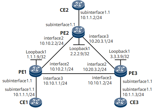
On the network shown in Figure 1, BGP AD VPLS is configured on PE1, PE2, and PE3. CE1 is connected to PE1; CE2 is connected to PE2; CE3 is connected to PE3. CE1, CE2, and CE3 are on one VPLS network.

Configuration Roadmap
The configuration roadmap is as follows:
Configure a routing protocol to enable connectivity between devices on a backbone network and configure basic MPLS functions.
Set up LSPs between PEs.
Enable MPLS L2VPN on each PE.
Enable BGP peers (PEs) to exchange VPLS information.
Create a VSI on every PE (set a VPLS ID and a VPN target) and configure BGP signaling.
Bind a VSI to the PE's AC interface connected to a CE.
Data Preparation
To complete the configuration, you need the following data:
IP address of each BGP peer
Name of a VSI on each PE
BGP AS number on each PE
BGP, the signaling protocol for a VSI
VPLS ID and VPN target on each PE
Interface to which a VSI is bound and VLAN ID on each interface
Procedure
- Configure an IGP. In this example, OSPF is used.
Assign an IP address to each interface on PEs as shown in Figure 1. Configure OSPF and advertise 32-bit loopback interface addresses (LSR IDs) of PE1, PE2, and PE3.
After the configurations are complete, run the display ip routing-table command on PE1, PE2, and PE3. They have learned routes from each other.
For detailed configurations, see Configuration Files in this section.
- Configure basic MPLS functions and LDP.
For detailed configurations, see Configuration Files in this section.
After the configurations are complete, run the display mpls ldp peer command on PE1, PE2, and PE3. The LDP peer relationships have been established between PE1 and PE2, between PE1 and PE3, and between PE2 and PE3. Run the display mpls ldp session command on each PE. LDP sessions have been established between them. Run the display mpls lsp command on each PE. The command output shows LDP LSPs that have been set up.
- Enable BGP peers to exchange VPLS information.
# Configure PE1.
[~PE1] bgp 100
[*PE1-bgp] peer 2.2.2.9 as-number 100
[*PE1-bgp] peer 3.3.3.9 as-number 100
[*PE1-bgp] peer 2.2.2.9 connect-interface loopback1
[*PE1-bgp] peer 3.3.3.9 connect-interface loopback1
[*PE1-bgp] l2vpn-ad-family
[*PE1-bgp-af-l2vpn-ad] peer 2.2.2.9 enable
[*PE1-bgp-af-l2vpn-ad] peer 3.3.3.9 enable
[*PE1-bgp-af-l2vpn-ad] quit
[*PE1-bgp] quit
[*PE1] commit
# Configure PE2.
[~PE2] bgp 100
[*PE2-bgp] peer 1.1.1.9 as-number 100
[*PE2-bgp] peer 3.3.3.9 as-number 100
[*PE2-bgp] peer 1.1.1.9 connect-interface loopback1
[*PE2-bgp] peer 3.3.3.9 connect-interface loopback1
[*PE2-bgp] l2vpn-ad-family
[*PE2-bgp-af-l2vpn-ad] peer 1.1.1.9 enable
[*PE2-bgp-af-l2vpn-ad] peer 3.3.3.9 enable
[*PE2-bgp-af-l2vpn-ad] quit
[*PE2-bgp] quit
[*PE2] commit
# Configure PE3.
[~PE3] bgp 100
[*PE3-bgp] peer 1.1.1.9 as-number 100
[*PE3-bgp] peer 2.2.2.9 as-number 100
[*PE3-bgp] peer 1.1.1.9 connect-interface loopback1
[*PE3-bgp] peer 2.2.2.9 connect-interface loopback1
[*PE3-bgp] l2vpn-ad-family
[*PE3-bgp-af-l2vpn-ad] peer 1.1.1.9 enable
[*PE3-bgp-af-l2vpn-ad] peer 2.2.2.9 enable
[*PE3-bgp-af-l2vpn-ad] quit
[*PE3-bgp] quit
[*PE3] commit
- Enable MPLS L2VPN on each PE.
# Configure PE1.
[~PE1] mpls l2vpn
[*PE1] commit
# Configure PE2.
[~PE2] mpls l2vpn
[*PE2] commit
# Configure PE3.
[~PE3] mpls l2vpn
[*PE3] commit
- Configure a VSI on each PE.
# Configure PE1.
[~PE1] vsi vplsad1
[*PE1-vsi-vplsad1]bgp-ad
[*PE1-vsi-vplsad1-bgpad] vpls-id 10.10.1.1:1
[*PE1-vsi-vplsad1-bgpad] vpn-target 100:1 import-extcommunity
[*PE1-vsi-vplsad1-bgpad] vpn-target 100:1 export-extcommunity
[*PE1-vsi-vplsad1-bgpad] quit
[*PE1-vsi-vplsad1] quit
[*PE1] commit
# Configure PE2.
[~PE2] vsi vplsad1
[*PE2-vsi-vplsad1]bgp-ad
[*PE2-vsi-vplsad1-bgpad] vpls-id 10.10.1.1:1
[*PE2-vsi-vplsad1-bgpad] vpn-target 100:1 import-extcommunity
[*PE2-vsi-vplsad1-bgpad] vpn-target 100:1 export-extcommunity
[*PE2-vsi-vplsad1-bgpad] quit
[*PE2-vsi-vplsad1] quit
[*PE2] commit
# Configure PE3.
[~PE3] vsi vplsad1
[*PE3-vsi-vplsad1]bgp-ad
[*PE3-vsi-vplsad1-bgpad] vpls-id 10.10.1.1:1
[*PE3-vsi-vplsad1-bgpad] vpn-target 100:1 import-extcommunity
[*PE3-vsi-vplsad1-bgpad] vpn-target 100:1 export-extcommunity
[*PE3-vsi-vplsad1-bgpad] quit
[*PE3-vsi-vplsad1] quit
[*PE3] commit
- Bind the VSI to an AC interface on each PE.
# Create a sub-interface on PE1; add this sub-interface to VLAN 10; bind this sub-interface to the VSI.
[~PE1] interface gigabitethernet0/1/0.1
[*PE1-GigabitEthernet0/1/0.1] vlan-type dot1q 10
[*PE1-GigabitEthernet0/1/0.1] l2 binding vsi vplsad1
[*PE1-GigabitEthernet0/1/0.1] quit
[*PE1] commit
# Create a sub-interface on PE2; add this sub-interface to VLAN 10; bind this sub-interface to the VSI.
[~PE2] interface gigabitethernet0/1/0.1
[*PE2-GigabitEthernet0/1/0.1] vlan-type dot1q 10
[*PE2-GigabitEthernet0/1/0.1] l2 binding vsi vplsad1
[*PE2-GigabitEthernet0/1/0.1] quit
[*PE2] commit
# Create a sub-interface on PE3; add this sub-interface to VLAN 10; bind this sub-interface to the VSI.
[~PE3] interface gigabitethernet0/1/0.1
[*PE3-GigabitEthernet0/1/0.1] vlan-type dot1q 10
[*PE3-GigabitEthernet0/1/00.1] l2 binding vsi vplsad1
[*PE3-GigabitEthernet0/1/0.1] quit
[*PE3] commit
- Configure each CE.
# Configure CE1.
[~CE1] interface gigabitethernet0/1/0.1
[*CE1-GigabitEthernet0/1/0.1] vlan-type dot1q 10
[*CE1-GigabitEthernet0/1/0.1] ip address 10.1.1.1 255.255.255.0
[*CE1-GigabitEthernet0/1/0.1] quit
[*CE1] commit
# Configure CE2.
[*CE2] interface gigabitethernet0/1/0.1
[*CE2-GigabitEthernet0/1/0.1] vlan-type dot1q 10
[*CE2-GigabitEthernet0/1/0.1] ip address 10.1.1.2 255.255.255.0
[*CE2-GigabitEthernet0/1/0.1] quit
[*CE2] commit
# Configure CE3.
[*CE3] interface gigabitethernet0/1/0.1
[*CE3-GigabitEthernet0/1/0.1] vlan-type dot1q 10
[*CE3-GigabitEthernet0/1/0.1] ip address 10.1.1.3 255.255.255.0
[*CE3-GigabitEthernet0/1/0.1] quit
[*CE3] commit
- Verify the configuration.
After the configuration, run the display vsi name vplsad1 verbose command on each PE. The VSI named vplsad1 is Up. In this VSI, PWs have been established successfully between PE1 and PE2, PE1 and PE3, and between PE2 and PE3.
<PE1> display vsi name vplsad1 verbose
 ***VSI Name               : vplsad1
    Administrator VSI      : no
    Isolate Spoken         : disable
    VSI Index              : 0
    PW Signaling           : ad
    Member Discovery Style : --
    Bridge-domain Mode     : disable
    PW MAC Learn Style     : unqualify
    Encapsulation Type     : vlan
    MTU                    : 1500
    Diffserv Mode          : uniform
    Service Class          : --
    Color                  : --
    DomainId               : 255
    Domain Name            :
    Ignore AcState         : disable
    Create Time            : 0 days, 18 hours, 5 minutes, 30 seconds
    VSI State              : up
    Resource Status        : --

    VPLS ID                : 10.10.1.1:1
    RD                     : 10.10.1.1:1
    Import vpn target      : 100:1
    Export vpn target      : 100:1
    VSI ID                 : 1.1.1.9

   *Peer Router ID         : 2.2.2.9
    VPLS ID                : 10.10.1.1:1
    SAII                   : 1.1.1.9
    TAII                   : 2.2.2.9
    VC Label               : 1024
    Peer Type              : dynamic
    Session                : up
    Tunnel ID              : 0x80003f
    Broadcast Tunnel ID    : 0x80003f
    CKey                   : 2
    NKey                   : 1

   *Peer Router ID         : 3.3.3.9
    VPLS ID                : 10.10.1.1:1
    SAII                   : 1.1.1.9
    TAII                   : 3.3.3.9
    VC Label               : 1025
    Peer Type              : dynamic
    Session                : up
    Tunnel ID              : 0x800033
    Broadcast Tunnel ID    : 0x800033
    CKey                   : 4
    NKey                   : 3

    Interface Name         : GigabitEthernet0/1/0.1
    State                  : up
    Last Up Time           : 2010/10/18 15:54:46
    Total Up Time          : 0 days, 17 hours, 58 minutes, 24 seconds

   **PW Information:

   *Peer Ip Address        : 3.3.3.9
    PW State               : up
    Local VC Label         : 1025
    Remote VC Label        : 1025
    PW Type                : label
    Tunnel ID              : 0x800033
    Broadcast Tunnel ID    : 0x800033
    Broad BackupTunnel ID  : 0x0
    Ckey                   : 0x4
    Nkey                   : 0x3
    Main PW Token          : 0x800033
    Slave PW Token         : 0x0
    Tnl Type               : LSP
    OutInterface           : GigabitEthernet0/1/8
    Backup OutInterface    :
    Stp Enable             : 0
    PW Last Up Time        : 2010/10/18 18:22:01
    PW Total Up Time       : 62 days, 6 hours, 48 minutes, 45 seconds
   *Peer Ip Address        : 2.2.2.9
    PW State               : up
    Local VC Label         : 1024
    Remote VC Label        : 1024
    PW Type                : label
    Tunnel ID              : 0x80003f
    Broadcast Tunnel ID    : 0x80003f
    Broad BackupTunnel ID  : 0x0
    Ckey                   : 0x2
    Nkey                   : 0x1
    Main PW Token          : 0x80003f
    Slave PW Token         : 0x0
    Tnl Type               : LSP
    OutInterface           : GigabitEthernet0/1/0
    Backup OutInterface    :
    Stp Enable             : 0
    PW Last Up Time        : 2010/10/18 18:24:23
    PW Total Up Time       : 38 days, 13 hours, 46 minutes, 13 seconds
# Configure CE1, CE2, and CE3 to ping each other. The ping operations are all successful. The following information shows that CE1 (10.1.1.1) successfully pings CE2 (10.1.1.2).
<CE1> ping 10.1.1.2
  PING 10.1.1.2: 56  data bytes, press CTRL_C to break
    Reply from 10.1.1.2: bytes=56 Sequence=1 ttl=255 time=140 ms
    Reply from 10.1.1.2: bytes=56 Sequence=2 ttl=255 time=140 ms
    Reply from 10.1.1.2: bytes=56 Sequence=3 ttl=255 time=140 ms
    Reply from 10.1.1.2: bytes=56 Sequence=4 ttl=255 time=190 ms
    Reply from 10.1.1.2: bytes=56 Sequence=5 ttl=255 time=110 ms

  --- 10.1.1.2 ping statistics ---
    5 packet(s) transmitted
    5 packet(s) received
    0.00% packet loss
    round-trip min/avg/max = 110/144/190 ms
Configuration Files
CE1 configuration file
#
 sysname CE1
#
interface GigabitEthernet0/1/0
 undo shutdown
#
interface GigabitEthernet0/1/0.1
 vlan-type dot1q 10
 ip address 10.1.1.1 255.255.255.0
#
return
CE2 configuration file
#
 sysname CE2
#
interface GigabitEthernet0/1/0
 undo shutdown
#
interface GigabitEthernet0/1/0.1
 vlan-type dot1q 10
 ip address 10.1.1.2 255.255.255.0
#
return
CE3 configuration file
#
 sysname CE3
#
interface GigabitEthernet0/1/0
 undo shutdown
#
interface GigabitEthernet0/1/0.1
 vlan-type dot1q 10
 ip address 10.1.1.3 255.255.255.0
#
return
PE1 configuration file
#
 sysname PE1
#
 mpls lsr-id 1.1.1.9
 mpls
#
 mpls l2vpn
#
vsi vplsad1
 bgp-ad
  vpls-id 10.10.1.1:1
  vpn-target 100:1 import-extcommunity
  vpn-target 100:1 export-extcommunity
#
mpls ldp
#
#
interface GigabitEthernet0/1/0
 undo shutdown
#
interface GigabitEthernet0/1/0.1
 vlan-type dot1q 10
 l2 binding vsi vplsad1
#
interface GigabitEthernet0/1/0
 ip address 10.10.2.1 255.255.255.0
 mpls
 mpls ldp
#
interface GigabitEthernet0/1/0
 ip address 10.10.1.1 255.255.255.0
 mpls
 mpls ldp
#
interface LoopBack1
 ip address 1.1.1.9 255.255.255.255
#
bgp 100
 peer 2.2.2.9 as-number 100
 peer 2.2.2.9 connect-interface LoopBack1
 peer 3.3.3.9 as-number 100
 peer 3.3.3.9 connect-interface LoopBack1
 #
 ipv4-family unicast
  peer 2.2.2.9 enable
  peer 3.3.3.9 enable
 #
 l2vpn-ad-family
  policy vpn-target
  peer 2.2.2.9 enable
  peer 3.3.3.9 enable
#
ospf 1
 area 0.0.0.0
  network 1.1.1.9 0.0.0.0
  network 10.10.1.0 0.0.0.255
  network 10.10.2.0 0.0.0.255
#
return
PE2 configuration file
#
 sysname PE2
#
 mpls lsr-id 2.2.2.9
 mpls
#
 mpls l2vpn
#
vsi vplsad1
 bgp-ad
  vpls-id 10.10.1.1:1
  vpn-target 100:1 import-extcommunity
  vpn-target 100:1 export-extcommunity
#
mpls ldp
#
#
interface GigabitEthernet0/1/0
 undo shutdown
#
interface GigabitEthernet0/1/0.1
 vlan-type dot1q 10
 l2 binding vsi vplsad1
#
interface GigabitEthernet0/1/0
 ip address 10.10.2.2 255.255.255.0
 mpls
 mpls ldp
#
interface GigabitEthernet0/1/8
 ip address 10.20.3.1 255.255.255.0
 mpls
 mpls ldp
#
interface LoopBack1
 ip address 2.2.2.9 255.255.255.255
#
bgp 100
 peer 1.1.1.9 as-number 100
 peer 1.1.1.9 connect-interface LoopBack1
 peer 3.3.3.9 as-number 100
 peer 3.3.3.9 connect-interface LoopBack1
 #
 ipv4-family unicast
  peer 1.1.1.9 enable
  peer 3.3.3.9 enable
 #
 l2vpn-ad-family
  policy vpn-target
  peer 1.1.1.9 enable
  peer 3.3.3.9 enable
#
ospf 1
 area 0.0.0.0
  network 2.2.2.9 0.0.0.0
  network 10.10.2.0 0.0.0.255
  network 10.20.3.0 0.0.0.255
#
return
PE3 configuration file
#
 sysname PE3
#
 mpls lsr-id 3.3.3.9
 mpls
#
 mpls l2vpn
#
vsi vplsad1
 bgp-ad
  vpls-id 10.10.1.1:1
  vpn-target 100:1 import-extcommunity
  vpn-target 100:1 export-extcommunity
#
mpls ldp
#
#
interface GigabitEthernet0/1/0
 undo shutdown
#
interface GigabitEthernet0/1/0.1
 vlan-type dot1q 10
 l2 binding vsi vplsad1
#
interface GigabitEthernet0/1/0
 ip address 10.20.3.2 255.255.255.0
 mpls
 mpls ldp
#
interface GigabitEthernet0/1/8
 ip address 10.10.1.2 255.255.255.0
 mpls
 mpls ldp
#
interface LoopBack1
 ip address 3.3.3.9 255.255.255.255
#
bgp 100
 peer 1.1.1.9 as-number 100
 peer 1.1.1.9 connect-interface LoopBack1
 peer 2.2.2.9 as-number 100
 peer 2.2.2.9 connect-interface LoopBack1
 #
 ipv4-family unicast
  peer 1.1.1.9 enable
  peer 2.2.2.9 enable
 #
 l2vpn-ad-family
  policy vpn-target
  peer 1.1.1.9 enable
  peer 2.2.2.9 enable
#
ospf 1
 area 0.0.0.0
  network 3.3.3.9 0.0.0.0
  network 10.20.3.0 0.0.0.255
  network 10.10.1.0 0.0.0.255
#
return