Example for Configuring Interworking Between LDP VPLS and BGP AD VPLS in HVPLS Mode
This section provides an example of configuring interworking between Label Distribution Protocol (LDP) virtual private LAN service (VPLS) and Border Gateway Protocol Auto-Discovery (BGP AD) VPLS in hierarchical virtual private LAN service (HVPLS) mode.
Networking Requirements
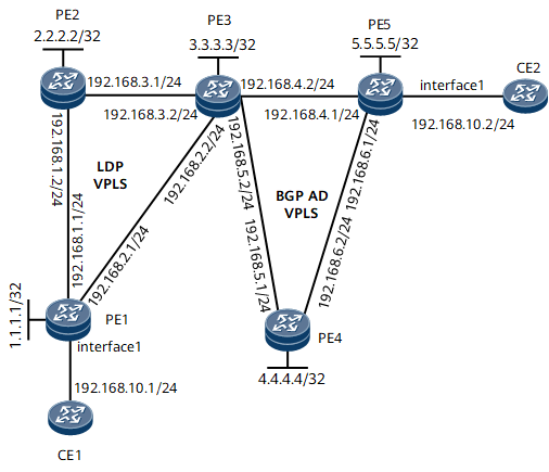
As shown in Figure 1, PE1 and PE2 support LDP VPLS, PE4 and PE5 support BGP AD VPLS, and PE3 supports both LDP VPLS and BGP AD VPLS. It is required that interworking between LDP VPLS and BGP AD VPLS be configured in HVPLS mode for CE1 and CE2 to communicate.
- Establish an LDP hub PW from PE1 to PE2 and from PE1 to PE3.
- Establish an LDP hub PW from PE2 to PE1 and from PE2 to PE3.
- Establish an LDP spoke PW from PE3 to PE1 and from PE3 to PE2. Establish a BGP AD hub PW from PE3 to PE4 and from PE3 to PE5.
- Establish a BGP AD hub PW from PE4 to PE3 and from PE4 to PE5.
- Establish a BGP AD hub PW from PE5 to PE3 and from PE5 to PE4.
Because traffic can be forwarded between spoke PWs, traffic may loop among PE1, PE2, and PE3. To prevent traffic loops, configure on PE3 traffic isolation between spoke PWs.

- Interface 1 in this example represents GE 0/1/2.
Device |
Interface |
IP Address |
|---|---|---|
PE1 |
GE 0/1/0 |
192.168.1.1/24 |
GE 0/1/1 |
192.168.2.1/24 |
|
GE 0/1/2 |
- |
|
Loopback 0 |
1.1.1.1/32 |
|
PE2 |
GE 0/1/0 |
192.168.1.2/24 |
GE 0/1/2 |
192.168.3.1/24 |
|
Loopback 0 |
2.2.2.2/32 |
|
PE3 |
GE 0/1/0 |
192.168.4.2/24 |
GE 0/1/1 |
192.168.2.2/24 |
|
GE 0/1/2 |
192.168.3.2/24 |
|
GE 0/1/3 |
192.168.5.2/24 |
|
Loopback 0 |
3.3.3.3/32 |
|
PE4 |
GE 0/1/1 |
192.168.6.2/24 |
GE 0/1/3 |
192.168.5.1/24 |
|
Loopback 0 |
4.4.4.4/32 |
|
PE5 |
GE 0/1/0 |
192.168.4.1/24 |
GE 0/1/1 |
192.168.6.1/24 |
|
GE 0/1/2 |
- |
|
Loopback 0 |
5.5.5.5/32 |
|
CE1 |
GE 0/1/2 |
- |
GE 0/1/2.1 |
192.168.10.1/24 |
|
CE2 |
GE 0/1/2 |
- |
GE 0/1/2.1 |
192.168.10.2/24 |
Configuration Roadmap
The configuration roadmap is as follows:
- Configure an IP address and a routing protocol for each interface so that all PEs can communicate at the network layer.
Configure Multiprotocol Label Switching (MPLS) and public tunnels.
Configure PE1, PE2, and PE3 to form an LDP VPLS network.
When you configure LDP PWs from PE3 to PE1 and PE2, specify peers as user provider edges (UPEs) for the PWs to function as spoke PWs. Then, configure traffic isolation between spoke PWs.
Configure PE3, PE4, and PE5 to form a BGP AD VPLS network.
Data Preparation
To complete the configuration, you need the following data:
IP address, Open Shortest Path First (OSPF) process ID, and OSPF area ID of each interface, and label switching router (LSR) ID of each PE
Virtual switch instance (VSI) name, VSI ID, VPLS ID, virtual private network (VPN) targets, and BGP AS number
Number and virtual local area network (VLAN) ID of each interface bound to a VSI
Procedure
- Configure an IP address and a routing protocol for each interface on the backbone network so that PEs can communicate at the network layer.
This example uses OSPF as the routing protocol. For details about specific configurations, see the following configuration files.
After the configuration is complete, run the display ip routing-table command on PEs to verify that the PEs have learned each other's loopback interface IP address.
- Configure MPLS and public tunnels.
This example uses LDP LSPs as public tunnels. For details about specific configurations, see the following configuration files.
After the configuration is complete, run the display mpls ldp session command on PEs to verify that peer relationships have been established; run the display mpls lsp command to verify that LSPs have been established.
- Configure PE1, PE2, and PE3 to form an LDP VPLS network.
# Configure PE1.
<PE1> system-view
[~PE1] mpls l2vpn
[*PE1-l2vpn] quit
[*PE1] vsi vsi1 static
[*PE1-vsi-vsi1] pwsignal ldp
[*PE1-vsi-vsi1-ldp] vsi-id 1
[*PE1-vsi-vsi1-ldp] peer 2.2.2.2
[*PE1-vsi-vsi1-ldp] peer 3.3.3.3
[*PE1-vsi-vsi1-ldp] quit
[*PE1-vsi-vsi1] quit
[*PE1] commit
# Configure PE2.
<PE2> system-view
[~PE2] mpls l2vpn
[*PE2-l2vpn] quit
[*PE2] vsi vsi1 static
[*PE2-vsi-vsi1] pwsignal ldp
[*PE2-vsi-vsi1-ldp] vsi-id 1
[*PE2-vsi-vsi1-ldp] peer 1.1.1.1
[*PE2-vsi-vsi1-ldp] peer 3.3.3.3
[*PE2-vsi-vsi1-ldp] quit
[*PE2-vsi-vsi1] quit
[*PE2] commit
# Configure PE3.
<PE3> system-view
[~PE3] mpls l2vpn
[*PE3-l2vpn] quit
[*PE3] vsi vsi1
[*PE3-vsi-vsi1] pwsignal ldp
[*PE3-vsi-vsi1-ldp] vsi-id 1
[*PE3-vsi-vsi1-ldp] peer 1.1.1.1 upe
[*PE3-vsi-vsi1-ldp] peer 2.2.2.2 upe
[*PE3-vsi-vsi1-ldp] quit
[*PE3-vsi-vsi1] isolate spoken
[*PE3-vsi-vsi1] quit
[*PE3] commit
# On PE1, bind the attachment circuit (AC) interface to the VSI.
[~PE1] interface gigabitethernet0/1/2.1
[*PE1-GigabitEthernet0/1/2.1] vlan-type dot1q 10
[*PE1-GigabitEthernet0/1/2.1] l2 binding vsi vsi1
[*PE1-GigabitEthernet0/1/2.1] quit
[*PE1] commit
- Configure PE3, PE4, and PE5 to form a BGP AD VPLS network.
Enable BGP peers to exchange VPLS information.
# Configure PE3.
[~PE3] bgp 100
[*PE3-bgp] peer 4.4.4.4 as-number 100
[*PE3-bgp] peer 4.4.4.4 connect-interface loopback0
[*PE3-bgp] peer 5.5.5.5 as-number 100
[*PE3-bgp] peer 5.5.5.5 connect-interface loopback0
[*PE3-bgp] l2vpn-ad-family
[*PE3-bgp-af-l2vpn-ad] peer 4.4.4.4 enable
[*PE3-bgp-af-l2vpn-ad] peer 5.5.5.5 enable
[*PE3-bgp-af-l2vpn-ad] quit
[*PE3-bgp] quit
[*PE3] commit
# Configure PE4.
<PE4> system-view
[~PE4] bgp 100
[*PE4-bgp] peer 3.3.3.3 as-number 100
[*PE4-bgp] peer 3.3.3.3 connect-interface loopback0
[*PE4-bgp] peer 5.5.5.5 as-number 100
[*PE4-bgp] peer 5.5.5.5 connect-interface loopback0
[*PE4-bgp] l2vpn-ad-family
[*PE4-bgp-af-l2vpn-ad] peer 3.3.3.3 enable
[*PE4-bgp-af-l2vpn-ad] peer 5.5.5.5 enable
[*PE4-bgp-af-l2vpn-ad] quit
[*PE4-bgp] quit
[*PE4] commit
# Configure PE5.
<PE5> system-view
[~PE5] bgp 100
[*PE5-bgp] peer 3.3.3.3 as-number 100
[*PE5-bgp] peer 3.3.3.3 connect-interface loopback0
[*PE5-bgp] peer 4.4.4.4 as-number 100
[*PE5-bgp] peer 4.4.4.4 connect-interface loopback0
[*PE5-bgp] l2vpn-ad-family
[*PE5-bgp-af-l2vpn-ad] peer 3.3.3.3 enable
[*PE5-bgp-af-l2vpn-ad] peer 4.4.4.4 enable
[*PE5-bgp-af-l2vpn-ad] quit
[*PE5-bgp] quit
[*PE5] commit
Create VSIs and configure the BGP AD signaling.
# Configure PE3.
[~PE3] vsi vsi1
[*PE3-vsi-vsi1] bgp-ad
[*PE3-vsi-vsi1--bgpad] vpls-id 192.168.0.0:1
[*PE3-vsi-vsi1--bgpad] vpn-target 100:1 import-extcommunity
[*PE3-vsi-vsi1--bgpad] vpn-target 100:1 export-extcommunity
[*PE3-vsi-vsi1--bgpad] quit
[*PE3-vsi-vsi1] quit
[*PE3] commit
On PE3, the LDP and BGP AD PWs must be configured in the same VSI.
# Configure PE4.
[~PE4] mpls l2vpn
[*PE4-l2vpn] quit
[*PE4] vsi vsi1
[*PE4-vsi-vsi1] bgp-ad
[*PE4-vsi-vsi1--bgpad] vpls-id 192.168.0.0:1
[*PE4-vsi-vsi1--bgpad] vpn-target 100:1 import-extcommunity
[*PE4-vsi-vsi1--bgpad] vpn-target 100:1 export-extcommunity
[*PE4-vsi-vsi1--bgpad] quit
[*PE4-vsi-vsi1] quit
[*PE4] commit
# Configure PE5.
[~PE5] mpls l2vpn
[*PE5-l2vpn] quit
[*PE5] vsi vsi1
[*PE5-vsi-vsi1] bgp-ad
[*PE5-vsi-vsi1--bgpad] vpls-id 192.168.0.0:1
[*PE5-vsi-vsi1--bgpad] vpn-target 100:1 import-extcommunity
[*PE5-vsi-vsi1--bgpad] vpn-target 100:1 export-extcommunity
[*PE5-vsi-vsi1--bgpad] quit
[*PE5-vsi-vsi1] quit
[*PE5] commit
# On PE5, bind the AC interface to the VSI.
[~PE5] interface gigabitethernet0/1/2.1
[*PE5-GigabitEthernet0/1/2.1] vlan-type dot1q 10
[*PE5-GigabitEthernet0/1/2.1] l2 binding vsi vsi1
[*PE5-GigabitEthernet0/1/2.1] quit
[*PE5] commit
- Configure CEs.
# Configure CE1.
<CE1> system-view
[~CE1] interface gigabitethernet0/1/2
[*CE1-GigabitEthernet0/1/2] undo shutdown
[*CE1-GigabitEthernet0/1/2] quit
[*CE1] interface gigabitethernet0/1/2.1
[*CE1-GigabitEthernet0/1/2.1] vlan-type dot1q 10
[*CE1-GigabitEthernet0/1/2.1] ip address 192.168.10.1 255.255.255.0
[*CE1-GigabitEthernet0/1/2.1] quit
[*CE1] commit
# Configure CE2.
<CE2> system-view
[~CE2] interface gigabitethernet0/1/2
[*CE2-GigabitEthernet0/1/2] undo shutdown
[*CE2-GigabitEthernet0/1/2] quit
[*CE2] interface gigabitethernet0/1/2.1
[*CE2-GigabitEthernet0/1/2.1] vlan-type dot1q 10
[*CE2-GigabitEthernet0/1/2.1] ip address 192.168.10.2 255.255.255.0
[*CE2-GigabitEthernet0/1/2.1] quit
[*CE2] commit
- Verify the configuration.
Ping CE2 from CE1. The command output shows that the ping is successful.
[~CE1] ping 192.168.10.2
  PING 192.168.10.2: 56  data bytes, press CTRL_C to break
    Reply from 192.168.10.2: bytes=56 Sequence=1 ttl=255 time=190 ms
    Reply from 192.168.10.2: bytes=56 Sequence=2 ttl=255 time=190 ms
    Reply from 192.168.10.2: bytes=56 Sequence=3 ttl=255 time=140 ms
    Reply from 192.168.10.2: bytes=56 Sequence=4 ttl=255 time=140 ms
    Reply from 192.168.10.2: bytes=56 Sequence=5 ttl=255 time=110 ms

  --- 192.168.10.2 ping statistics ---
    5 packet(s) transmitted
    5 packet(s) received
    0.00% packet loss
    round-trip min/avg/max = 110/154/190 ms
Configuration Files
PE1 configuration file
#
sysname PE1
#
mpls lsr-id 1.1.1.1
mpls
#
mpls l2vpn
#
vsi vsi1 static
 pwsignal ldp
  vsi-id 1
  peer 2.2.2.2
  peer 3.3.3.3
#
mpls ldp
#
interface GigabitEthernet0/1/0
 undo shutdown
 ip address 192.168.1.1 255.255.255.0
 mpls
 mpls ldp
#
interface GigabitEthernet0/1/1
 undo shutdown
 ip address 192.168.2.1 255.255.255.0
 mpls
 mpls ldp
#
interface GigabitEthernet0/1/2.1
 vlan-type dot1q 10
 l2 binding vsi vsi1
#
interface LoopBack0
 ip address 1.1.1.1 255.255.255.255
#
ospf 1
 area 0.0.0.0
  network 1.1.1.1 0.0.0.0
  network 192.168.1.0 0.0.0.255
  network 192.168.2.0 0.0.0.255
#
return
PE2 configuration file
#
sysname PE2
#
mpls lsr-id 2.2.2.2
mpls
#
mpls l2vpn
#
vsi vsi1 static
 pwsignal ldp
  vsi-id 1
  peer 1.1.1.1
  peer 3.3.3.3
#
mpls ldp
#
interface GigabitEthernet0/1/0
 undo shutdown
 ip address 192.168.1.2 255.255.255.0
 mpls
 mpls ldp
#
interface GigabitEthernet0/1/2
 undo shutdown
 ip address 192.168.3.1 255.255.255.0
 mpls
 mpls ldp
#
interface LoopBack0
 ip address 2.2.2.2 255.255.255.255
#
ospf 1
 area 0.0.0.0
  network 2.2.2.2 0.0.0.0
  network 192.168.1.0 0.0.0.255
  network 192.168.3.0 0.0.0.255
#
return
PE3 configuration file
#
sysname PE3
#
mpls lsr-id 3.3.3.3
mpls
#
mpls l2vpn
#
vsi vsi1
 pwsignal ldp
  vsi-id 1
  peer 1.1.1.1 upe
  peer 2.2.2.2 upe
 bgp-ad
  vpls-id 192.168.0.0:1
  vpn-target 100:1 import-extcommunity
  vpn-target 100:1 export-extcommunity
 isolate spoken
#
mpls ldp
#
interface GigabitEthernet0/1/0
 undo shutdown
 ip address 192.168.4.2 255.255.255.0
 mpls
 mpls ldp
#
interface GigabitEthernet0/1/1
 undo shutdown
 ip address 192.168.2.2 255.255.255.0
 mpls
 mpls ldp
#
interface GigabitEthernet0/1/2
 undo shutdown
 ip address 192.168.3.2 255.255.255.0
 mpls
 mpls ldp
#
interface GigabitEthernet0/1/3
 undo shutdown
 ip address 192.168.5.2 255.255.255.0
 mpls
 mpls ldp
#
interface LoopBack0
 ip address 3.3.3.3 255.255.255.255
#
bgp 100
 peer 4.4.4.4 as-number 100
 peer 4.4.4.4 connect-interface LoopBack0
 peer 5.5.5.5 as-number 100
 peer 5.5.5.5 connect-interface LoopBack0
 #
 ipv4-family unicast
  peer 4.4.4.4 enable
  peer 5.5.5.5 enable
 #
 l2vpn-ad-family
  policy vpn-target
  peer 4.4.4.4 enable
  peer 5.5.5.5 enable
#
ospf 1
 area 0.0.0.0
  network 3.3.3.3 0.0.0.0
  network 192.168.2.0 0.0.0.255
  network 192.168.3.0 0.0.0.255
  network 192.168.4.0 0.0.0.255
  network 192.168.5.0 0.0.0.255
#
return
PE4 configuration file
#
sysname PE4
#
mpls lsr-id 4.4.4.4
mpls
#
mpls l2vpn
#
vsi vsi1
 bgp-ad
  vpls-id 192.168.0.0:1
  vpn-target 100:1 import-extcommunity
  vpn-target 100:1 export-extcommunity
#
mpls ldp
#
interface GigabitEthernet0/1/1
 undo shutdown
 ip address 192.168.6.2 255.255.255.0
 mpls
 mpls ldp
#
interface GigabitEthernet0/1/3
 undo shutdown
 ip address 192.168.5.1 255.255.255.0
 mpls
 mpls ldp
#
interface LoopBack0
 ip address 4.4.4.4 255.255.255.255
#
bgp 100
 peer 3.3.3.3 as-number 100
 peer 3.3.3.3 connect-interface LoopBack0
 peer 5.5.5.5 as-number 100
 peer 5.5.5.5 connect-interface LoopBack0
 #
 ipv4-family unicast
  peer 3.3.3.3 enable
  peer 5.5.5.5 enable
 #
 l2vpn-ad-family
  policy vpn-target
  peer 3.3.3.3 enable
  peer 5.5.5.5 enable
#
ospf 1
 area 0.0.0.0
  network 4.4.4.4 0.0.0.0
  network 192.168.5.0 0.0.0.255
  network 192.168.6.0 0.0.0.255
#
return
PE5 configuration file
#
sysname PE5
#
mpls lsr-id 5.5.5.5
mpls
#
mpls l2vpn
#
vsi vsi1
 bgp-ad
  vpls-id 192.168.0.0:1
  vpn-target 100:1 import-extcommunity
  vpn-target 100:1 export-extcommunity
#
mpls ldp
#
interface GigabitEthernet0/1/0
 undo shutdown
 ip address 192.168.4.1 255.255.255.0
 mpls
 mpls ldp
#
interface GigabitEthernet0/1/1
 undo shutdown
 ip address 192.168.6.1 255.255.255.0
 mpls
 mpls ldp
#
interface GigabitEthernet0/1/2
 undo shutdown
#
interface GigabitEthernet0/1/2.1
 vlan-type dot1q 10
 l2 binding vsi vsi1
#
interface LoopBack0
 ip address 5.5.5.5 255.255.255.255
#
bgp 100
 peer 3.3.3.3 as-number 100
 peer 3.3.3.3 connect-interface LoopBack0
 peer 4.4.4.4 as-number 100
 peer 4.4.4.4 connect-interface LoopBack0
 #
 ipv4-family unicast
  peer 3.3.3.3 enable
  peer 4.4.4.4 enable
 #
 l2vpn-ad-family
  policy vpn-target
  peer 3.3.3.3 enable
  peer 4.4.4.4 enable
#
ospf 1
 area 0.0.0.0
  network 5.5.5.5 0.0.0.0
  network 192.168.4.0 0.0.0.255
  network 192.168.6.0 0.0.0.255
#
return
CE1 configuration file
#
sysname CE1
#
interface GigabitEthernet0/1/2
 undo shutdown
#
interface GigabitEthernet0/1/2.1
 vlan-type dot1q 10
 ip address 192.168.10.1 255.255.255.0
#
return
CE2 configuration file
#
sysname CE2
#
interface GigabitEthernet0/1/2
 undo shutdown
#
interface GigabitEthernet0/1/2.1
 vlan-type dot1q 10
 ip address 192.168.10.2 255.255.255.0
#
return