Example for Configuring a Dynamic VPWS SS-PW over an SRv6 TE Policy
This section provides an example for configuring a dynamic VPWS SS-PW over an SRv6 TE Policy.
Networking Requirements
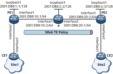
On the network shown in Figure 1, PE1, the P, and PE2 are in the same AS and run IS-IS to implement IPv6 network connectivity. It is required that a bidirectional SRv6 TE Policy be deployed between PE1 and PE2 to carry VPWS PWs.

Configuration Roadmap
The configuration roadmap is as follows:
Enable IPv6 forwarding and configure an IPv6 address for each interface on PE1, the P, and PE2.
Enable IS-IS, configure an IS-IS level, and specify a network entity title (NET) on PE1, the P, and PE2.
- Configure SRv6 SIDs and enable IS-IS SRv6 on PE1, the P, and PE2.
- Set up LDP sessions between PEs.
- Enable MPLS L2VPN on PEs and establish a VPWS PW.
Data Preparation
To complete the configuration, you need the following data:
Procedure
- Enable IPv6 forwarding and configure an IPv6 address for each interface.
# Configure PE1. The configurations of the P and PE2 are similar to the configuration of PE1. For configuration details, see Configuration Files in this section.
<HUAWEI> system-view
[~HUAWEI] sysname PE1
[*HUAWEI] commit
[~PE1] interface gigabitethernet 0/1/0
[~PE1-GigabitEthernet0/1/0] ipv6 enable
[*PE1-GigabitEthernet0/1/0] ipv6 address 2001:DB8:10::1 64
[*PE1-GigabitEthernet0/1/0] quit
[*PE1] interface LoopBack 1
[*PE1-LoopBack1] ip address 1.1.1.1 32
[*PE1-LoopBack1] ipv6 enable
[*PE1-LoopBack1] ipv6 address 2001:DB8:1::1 128
[*PE1-LoopBack1] quit
[*PE1] commit
Configure an IPv4 address for the loopback interface, as the L2VPN source address needs to be an IPv4 address.
- Configure IS-IS.
# Configure PE1.
[~PE1] isis 1
[*PE1-isis-1] is-level level-1
[*PE1-isis-1] cost-style wide
[*PE1-isis-1] network-entity 10.0000.0000.0001.00
[*PE1-isis-1] ipv6 enable topology ipv6
[*PE1-isis-1] quit
[*PE1] interface gigabitethernet 0/1/0
[*PE1-GigabitEthernet0/1/0] isis enable 1
[*PE1-GigabitEthernet0/1/0] isis ipv6 enable 1
[*PE1-GigabitEthernet0/1/0] quit
[*PE1] interface loopback1
[*PE1-LoopBack1] isis enable 1
[*PE1-LoopBack1] isis ipv6 enable 1
[*PE1-LoopBack1] quit
[*PE1] commit
# Configure the P.
[~P] isis 1
[*P-isis-1] is-level level-1
[*P-isis-1] cost-style wide
[*P-isis-1] network-entity 10.0000.0000.0002.00
[*P-isis-1] ipv6 enable topology ipv6
[*P-isis-1] quit
[*P] interface gigabitethernet 0/1/0
[*P-GigabitEthernet0/1/0] isis enable 1
[*P-GigabitEthernet0/1/0] isis ipv6 enable 1
[*P-GigabitEthernet0/1/0] quit
[*P] interface gigabitethernet 0/1/8
[*P-GigabitEthernet0/1/8] isis enable 1
[*P-GigabitEthernet0/1/8] isis ipv6 enable 1
[*P-GigabitEthernet0/1/8] quit
[*P] interface loopback1
[*P-LoopBack1] isis enable 1
[*P-LoopBack1] isis ipv6 enable 1
[*P-LoopBack1] quit
[*P] commit
# Configure PE2.
[~PE2] isis 1
[*PE2-isis-1] is-level level-1
[*PE2-isis-1] cost-style wide
[*PE2-isis-1] network-entity 10.0000.0000.0003.00
[*PE2-isis-1] ipv6 enable topology ipv6
[*PE2-isis-1] quit
[*PE2] interface gigabitethernet 0/1/0
[*PE2-GigabitEthernet0/1/0] isis enable 1
[*PE2-GigabitEthernet0/1/0] isis ipv6 enable 1
[*PE2-GigabitEthernet0/1/0] quit
[*PE2] interface loopback1
[*PE2-LoopBack1] isis enable 1
[*PE2-LoopBack1] isis ipv6 enable 1
[*PE2-LoopBack1] quit
[*PE2] commit
After the configuration is complete, perform the following operations to verify the IS-IS configuration:
# Display IS-IS neighbor information. The following example uses the command output on PE1.
[~PE1] display isis peer
                          Peer information for ISIS(1)

  System Id     Interface         Circuit Id        State HoldTime Type     PRI
--------------------------------------------------------------------------------
0000.0000.0002* GE0/1/0           0000.0000.0002.01  Up   8s       L1       64

Total Peer(s): 1
- Configure SRv6 SIDs.
# Configure PE1.
[~PE1] segment-routing ipv6
[*PE1-segment-routing-ipv6] encapsulation source-address 2001:DB8:1::1
[*PE1-segment-routing-ipv6] locator PE1 ipv6-prefix 2001:DB8:100:: 64 static 32
[*PE1-segment-routing-ipv6-locator] opcode ::10 end psp-usp-usd
[*PE1-segment-routing-ipv6-locator] quit
[*PE1-segment-routing-ipv6] quit
[*PE1] commit
[~PE1] isis 1
[~PE1-isis-1] segment-routing ipv6 locator PE1 auto-sid-disable
[*PE1-isis-1] commit
[~PE1-isis-1] quit
# Configure the P.
[~P] segment-routing ipv6
[*P-segment-routing-ipv6] encapsulation source-address 2001:DB8:2::2
[*P-segment-routing-ipv6] locator P ipv6-prefix 2001:DB8:120:: 64 static 32
[*P-segment-routing-ipv6-locator] opcode ::20 end psp-usp-usd
[*P-segment-routing-ipv6-locator] quit
[*P-segment-routing-ipv6] quit
[~P] isis 1
[~P-isis-1] segment-routing ipv6 locator P auto-sid-disable
[*P-isis-1] commit
[~P-isis-1] quit
# Configure PE2.
[~PE2] segment-routing ipv6
[*PE2-segment-routing-ipv6] encapsulation source-address 2001:DB8:3::3
[*PE2-segment-routing-ipv6] locator PE2 ipv6-prefix 2001:DB8:130:: 64 static 32
[*PE2-segment-routing-ipv6-locator] opcode ::30 end psp-usp-usd
[*PE2-segment-routing-ipv6-locator] quit
[*PE2-segment-routing-ipv6] quit
[*PE2] commit
[~PE2] isis 1
[~PE2-isis-1] segment-routing ipv6 locator PE2 auto-sid-disable
[*PE2-isis-1] commit
[~PE2-isis-1] quit
After the configuration is complete, run the display segment-routing ipv6 locator [ locator-name ] verbose command to check SRv6 locator information.
The following example uses the configuration on PE1.
[~PE1] display segment-routing ipv6 locator verbose

                        Locator Configuration Table
                        ---------------------------

LocatorName   : PE1                                       LocatorID     : 1
IPv6Prefix    : 2001:DB8:100::                            PrefixLength  : 64
Block         : --                                        BlockLength   : 0
NodeID        : --                                        NodeIdLength  : 0
ComprStaticLen: 0                                         StaticLength  : 32
ArgsLength    : 0                                         Reference     : 2
AutoCSIDPoolID: 0                                         ComprDynLength: 0
AutoCSIDBegin : --
AutoCSIDEnd   : --
StaticCSIDBegin: --
StaticCSIDEnd : --
AutoSIDPoolID : 8197                                      DynLength     : 32
AutoSIDBegin  : 2001:DB8:100::1:0:0
AutoSIDEnd    : 2001:DB8:100:0:FFFF:FFFF:FFFF:FFFF
StaticSIDBegin: 2001:DB8:100::1
StaticSIDEnd  : 2001:DB8:100::FFFF:FFFF

Total Locator(s): 1
Run the display segment-routing ipv6 local-sid end forwarding command to check information about the SRv6 local SID table.
[~PE1] display segment-routing ipv6 local-sid end forwarding
                    My Local-SID End Forwarding Table
                    ---------------------------------

SID         : 2001:DB8:100::10/128                         FuncType : End
Flavor      : PSP USP USD
LocatorName : PE1                                          LocatorID: 1
ProtocolType: STATIC                                       ProcessID: --
UpdateTime  : 2021-09-22 09:47:26.426

Total SID(s): 1
[~PE2] display segment-routing ipv6 local-sid end forwarding
                    My Local-SID End Forwarding Table
                    ---------------------------------

SID         : 2001:DB8:130::30/128                         FuncType : End
Flavor      : PSP USP USD
LocatorName : PE2                                          LocatorID: 1
ProtocolType: STATIC                                       ProcessID: --
UpdateTime  : 2021-09-22 09:47:26.426

Total SID(s): 1
[~P] display segment-routing ipv6 local-sid end forwarding
                    My Local-SID End Forwarding Table
                    ---------------------------------

SID         : 2001:DB8:120::20/128                         FuncType : End
Flavor      : PSP USP USD
LocatorName : P                                            LocatorID: 1
ProtocolType: STATIC                                       ProcessID: --
UpdateTime  : 2021-09-22 09:47:26.426

Total SID(s): 1
- Configure an SRv6 TE Policy.
# Configure PE1.
[~PE1] segment-routing ipv6
[*PE1-segment-routing-ipv6] segment-list list1
[*PE1-segment-routing-ipv6-segment-list-list1] index 5 sid ipv6 2001:DB8:120::20
[*PE1-segment-routing-ipv6-segment-list-list1] index 10 sid ipv6 2001:DB8:130::30
[*PE1-segment-routing-ipv6-segment-list-list1] commit
[~PE1-segment-routing-ipv6-segment-list-list1] quit
[~PE1-segment-routing-ipv6] srv6-te-policy locator PE1
[*PE1-segment-routing-ipv6] srv6-te policy policy1 endpoint 2001:DB8:3::3 color 101
[*PE1-segment-routing-ipv6-policy-policy1] encapsulation-mode encaps
[*PE1-segment-routing-ipv6-policy-policy1] binding-sid 2001:DB8:100::450
[*PE1-segment-routing-ipv6-policy-policy1] candidate-path preference 100
[*PE1-segment-routing-ipv6-policy-policy1-path] segment-list list1
[*PE1-segment-routing-ipv6-policy-policy1-path] commit
[~PE1-segment-routing-ipv6-policy-policy1-path] quit
[~PE1-segment-routing-ipv6-policy-policy1] quit
[~PE1-segment-routing-ipv6] quit
# Configure PE2.
[~PE2] segment-routing ipv6
[*PE2-segment-routing-ipv6] segment-list list1
[*PE2-segment-routing-ipv6-segment-list-list1] index 5 sid ipv6 2001:DB8:120::20
[*PE2-segment-routing-ipv6-segment-list-list1] index 10 sid ipv6 2001:DB8:100::10
[*PE2-segment-routing-ipv6-segment-list-list1] commit
[~PE2-segment-routing-ipv6-segment-list-list1] quit
[~PE2-segment-routing-ipv6] srv6-te-policy locator PE2
[*PE2-segment-routing-ipv6] srv6-te policy policy1 endpoint 2001:DB8:1::1 color 101
[*PE2-segment-routing-ipv6-policy-policy1] encapsulation-mode encaps
[*PE2-segment-routing-ipv6-policy-policy1] binding-sid 2001:DB8:130::350
[*PE2-segment-routing-ipv6-policy-policy1] candidate-path preference 100
[*PE2-segment-routing-ipv6-policy-policy1-path] segment-list list1
[*PE2-segment-routing-ipv6-policy-policy1-path] commit
[~PE2-segment-routing-ipv6-policy-policy1-path] quit
[~PE2-segment-routing-ipv6-policy-policy1] quit
[~PE2-segment-routing-ipv6] quit
After the configuration is complete, run the display srv6-te policy command to check SRv6 TE Policy information.
The following example uses the command output on PE1.
[~PE1] display srv6-te policy PolicyName : policy1 Color : 101 Endpoint : 2001:DB8:3::3 TunnelId : 1 Binding SID : 2001:DB8:100::450 TunnelType : SRv6-TE Policy DelayTimerRemain : - Policy State : Up State Change Time : 2020-03-03 02:32:11 Admin State : Up Traffic Statistics : Disable Backup Hot-Standby : Disable BFD : Disable Candidate-path Count : 1 Candidate-path Preference : 100 Path State : Active Path Type : Primary Protocol-Origin : Configuration(30) Originator : 0, 0.0.0.0 Discriminator : 100 Binding SID : 2001:DB8:100::450 GroupId : 1 Policy Name : policy1 Template ID : 0 Path Verification : Disable DelayTimerRemain : - Segment-List Count : 1 Segment-List : list1 Segment-List ID : 1 XcIndex : 1 List State : Up DelayTimerRemain : - Verification State : - SuppressTimeRemain : - PMTU : 9600 Active PMTU : 9600 Weight : 1 BFD State : - SID : 2001:DB8:120::20 2001:DB8:130::30 - Establish an LDP session.
Establish a remote session between PE1 and PE2.
# Configure PE1.
[~PE1] mpls ldp
[*PE1-mpls-ldp] quit
[*PE1] mpls ldp remote-peer 3.3.3.3
[*PE1-mpls-ldp-remote-3.3.3.3] remote-ip 3.3.3.3
[*PE1-mpls-ldp-remote-3.3.3.3] quit
[*PE1-mpls-ldp-remote-3.3.3.3] commit
# Configure PE2.
[~PE2] mpls ldp
[*PE2-mpls-ldp] quit
[*PE2] mpls ldp remote-peer 1.1.1.1
[*PE2-mpls-ldp-remote-1.1.1.1] remote-ip 1.1.1.1
[*PE2-mpls-ldp-remote-1.1.1.1] quit
[*PE2-mpls-ldp-remote-1.1.1.1] commit
After the configuration is complete, an LDP session is successfully set up between the PEs.
The following example uses the command output on PE1.
[~PE1] display mpls ldp session
 LDP Session(s) in Public Network
 Codes: LAM(Label Advertisement Mode), SsnAge Unit(DDDD:HH:MM)
 An asterisk (*) before a session means the session is being deleted.

--------------------------------------------------------------------------
 PeerID             Status      LAM  SsnRole  SsnAge       KASent/Rcv
--------------------------------------------------------------------------
 3.3.3.3:0          Operational DU   Passive  000:00:00    4/5
--------------------------------------------------------------------------
TOTAL: 1 Session(s) Found.
- Configure a tunnel policy and establish a VPWS PW.
# Configure PE1.
[~PE1] tunnel-policy policy1
[*PE1-tunnel-policy-policy1] tunnel select-seq ipv6 srv6-te-policy load-balance-number 1
[*PE1-tunnel-policy-policy1] quit
[*PE1] mpls l2vpn
[*PE1-l2vpn] quit
[*PE1] interface gigabitethernet 0/1/8
[*PE1-GigabitEthernet0/1/8] mpls l2vc 3.3.3.3 10 tunnel-policy policy1 endpoint 2001:DB8:3::3 color 101
[*PE1-GigabitEthernet0/1/8] undo shutdown
[*PE1-GigabitEthernet0/1/8] quit
[*PE1-GigabitEthernet0/1/8] commit
# Configure PE2.
[~PE2] tunnel-policy policy1
[*PE2-tunnel-policy-policy1] tunnel select-seq ipv6 srv6-te-policy load-balance-number 1
[*PE2-tunnel-policy-policy1] quit
[*PE2] mpls l2vpn
[*PE2-l2vpn] quit
[*PE2] interface gigabitethernet 0/1/8
[*PE2-GigabitEthernet0/1/8] mpls l2vc 1.1.1.1 10 tunnel-policy policy1 endpoint 2001:DB8:1::1 color 101
[*PE2-GigabitEthernet0/1/8] undo shutdown
[*PE2-GigabitEthernet0/1/8] quit
[*PE2-GigabitEthernet0/1/8] commit
# Configure CE1.
[~CE1] interface gigabitethernet 0/1/0
[*CE1-GigabitEthernet0/1/0] ip address 10.10.1.1 24
[*CE1-GigabitEthernet0/1/0] undo shutdown
[*CE1-GigabitEthernet0/1/0] quit
[*CE1-GigabitEthernet0/1/0] commit
Configure CE2.
[~CE2] interface gigabitethernet 0/1/0
[*CE2-GigabitEthernet0/1/0] ip address 10.10.1.2 24
[*CE2-GigabitEthernet0/1/0] undo shutdown
[*CE2-GigabitEthernet0/1/0] quit
[*CE2-GigabitEthernet0/1/0] commit
- Verify the configuration.
View VPWS PW information on PEs. The command output shows that a VC has been established and its status is up.
The following example uses the command output on PE1.
<PE1> display mpls l2vc interface gigabitethernet 0/1/8
*client interface       : GigabitEthernet0/1/8 is up
  Administrator PW       : no
  session state          : up
  AC status              : up
  VC state               : up
  Label state            : 0
  Token state            : 0
  VC ID                  : 10
  VC type                : Ethernet
  destination            : 3.3.3.3
  local group ID         : 0         remote group ID      : 0
  local VC label         : 18        remote VC label      : 18
  local AC OAM State     : up
  local PSN OAM State    : up
  local forwarding state : forwarding
  local status code      : 0x0 (forwarding)
  remote AC OAM State    : up
  remote PSN OAM state   : up
  remote forwarding state: forwarding
  remote status code     : 0x0 (forwarding)
  ignore standby state   : no
  BFD for PW             : unavailable
  VCCV State             : --
  manual fault           : not set
active state           : active
 forwarding entry       : exist
 OAM Protocol           : --
 OAM Status             : --
 OAM Fault Type         : --
 PW APS ID              : --
 PW APS Status          : --
 TTL Value              : 1
 link state             : up
 local VC MTU           : 1500      remote VC MTU        : 1500
 local VCCV             : alert ttl lsp-ping bfd
 remote VCCV            : alert ttl lsp-ping bfd
 local control word     : disable   remote control word  : disable
 tunnel policy name     : --
 PW template name       : --
 primary or secondary   : primary
 load balance type      : flow
 Access-port            : false
 Switchover Flag        : false
 VC tunnel info         : 1 tunnels
    NO.0 TNL type       : srv6tepolicy, TNL ID : 0x000000003400000001
 create time            : 0 days, 0 hours, 6 minutes, 29 seconds
 up time                : 0 days, 0 hours, 5 minutes, 21 seconds
 last change time       : 0 days, 0 hours, 5 minutes, 21 seconds
 VC last up time        : 2021/2/03 15:50:41
 VC total up time       : 0 days, 0 hours, 5 minutes, 21 seconds
 CKey                   : 1
 NKey                   : 1493172332
 PW redundancy mode     : frr
 AdminPw interface      : --
 AdminPw link state     : --
 Forward state          : send inactive, receive inactive
 Diffserv Mode          : uniform
 Service Class          : --
 Color                  : --
 DomainId               : --
 Domain Name            : --
CE1 and CE2 can ping each other.
<CE1> ping 10.10.1.2
  PING 10.10.1.2: 56  data bytes, press CTRL_C to break
    Reply from 10.10.1.2: bytes=56 Sequence=1 ttl=255 time=125 ms
    Reply from 10.10.1.2: bytes=56 Sequence=2 ttl=255 time=125 ms
    Reply from 10.10.1.2: bytes=56 Sequence=3 ttl=255 time=94 ms
    Reply from 10.10.1.2: bytes=56 Sequence=4 ttl=255 time=125 ms
    Reply from 10.10.1.2: bytes=56 Sequence=5 ttl=255 time=125 ms
  --- 10.10.1.2 ping statistics ---
    5 packet(s) transmitted
    5 packet(s) received
    0.00% packet loss
    round-trip min/avg/max = 94/118/125 ms
Configuration Files
-
# sysname CE1 # interface GigabitEthernet0/1/0 undo shutdown ip address 10.10.1.1 255.255.255.0 # return -
#
sysname PE1
#
mpls lsr-id 1.1.1.1
#
mpls
#
mpls l2vpn
#
mpls ldp
#
mpls ldp remote-peer 3.3.3.3
 remote-ip 3.3.3.3
#
segment-routing ipv6
 encapsulation source-address 2001:DB8:1::1
 locator PE1 ipv6-prefix 2001:DB8:100:: 64 static 32
  opcode ::10 end psp-usp-usd
 srv6-te-policy locator PE1
 segment-list list1
  index 5 sid ipv6 2001:DB8:120::20
  index 10 sid ipv6 2001:DB8:130::30
 srv6-te policy policy1 endpoint 2001:DB8:3::3 color 101
  encapsulation-mode encaps
  binding-sid 2001:DB8:100::450
  candidate-path preference 100
   segment-list list1
#
isis 1
 is-level level-1
 cost-style wide
 network-entity 10.0000.0000.0001.00
 #
 ipv6 enable topology ipv6
 segment-routing ipv6 locator PE1 auto-sid-disable
 #
#
interface GigabitEthernet0/1/0
 undo shutdown
 isis enable 1
 ipv6 enable
 ipv6 address 2001:DB8:10::1/64
 isis ipv6 enable 1
#
interface GigabitEthernet0/1/8
 undo shutdown
 mpls l2vc 3.3.3.3 10 tunnel-policy policy1 endpoint 2001:DB8:3::3 color 101
#
interface LoopBack1
 isis enable 1
 ipv6 enable
 ip address 1.1.1.1 255.255.255.255
 ipv6 address 2001:DB8:1::1/128
 isis ipv6 enable 1
#
tunnel-policy policy1
 tunnel select-seq ipv6 srv6-te-policy load-balance-number 1
#
return
-
#
sysname P
#
segment-routing ipv6
 encapsulation source-address 2001:DB8:2::2
 locator P ipv6-prefix 2001:DB8:120:: 64 static 32
  opcode ::20 end psp-usp-usd
#
isis 1
 is-level level-1
 cost-style wide
 network-entity 10.0000.0000.0002.00
 #
 ipv6 enable topology ipv6
 segment-routing ipv6 locator P auto-sid-disable
 #
#
interface GigabitEthernet0/1/0
 undo shutdown
 isis enable 1
 ipv6 enable
 ipv6 address 2001:DB8:10::2/64
 isis ipv6 enable 1
#
interface GigabitEthernet0/1/8
 undo shutdown
 isis enable 1
 ipv6 enable
 ipv6 address 2001:DB8:20::1/64
 isis ipv6 enable 1
#
interface LoopBack1
 isis enable 1
 ipv6 enable
 ipv6 address 2001:DB8:2::2/128
 isis ipv6 enable 1
#
return
-
#
sysname PE2
#
 mpls lsr-id 3.3.3.3
#
mpls
#
mpls l2vpn
#
mpls ldp
#
mpls ldp remote-peer 1.1.1.1
 remote-ip 1.1.1.1
#
segment-routing ipv6
 encapsulation source-address 2001:DB8:3::3
 locator PE2 ipv6-prefix 2001:DB8:130:: 64 static 32
  opcode ::30 end psp-usp-usd
 srv6-te-policy locator PE2
 segment-list list1
  index 5 sid ipv6 2001:DB8:120::20
  index 10 sid ipv6 2001:DB8:100::10
 srv6-te policy policy1 endpoint 2001:DB8:1::1 color 101
  encapsulation-mode encaps
  binding-sid 2001:DB8:130::350
  candidate-path preference 100
   segment-list list1
#
isis 1
 is-level level-1
 cost-style wide
 network-entity 10.0000.0000.0003.00
#
 ipv6 enable topology ipv6
 segment-routing ipv6 locator PE2 auto-sid-disable
 #
#
interface GigabitEthernet0/1/0
 undo shutdown
 isis enable 1
 ipv6 enable
 ipv6 address 2001:DB8:20::2/64
 isis ipv6 enable 1
#
interface GigabitEthernet0/1/8
 undo shutdown
 mpls l2vc 1.1.1.1 10 tunnel-policy policy1 endpoint 2001:DB8:1::1 color 101
#
interface LoopBack1
 isis enable 1
 ipv6 enable
 ip address 3.3.3.3 255.255.255.255
 ipv6 address 2001:DB8:3::3/128
 isis ipv6 enable 1
#
tunnel-policy policy1
 tunnel select-seq ipv6 srv6-te-policy load-balance-number 1
#
return
-
#
sysname CE2
#
interface GigabitEthernet0/1/0
 undo shutdown
 ip address 10.10.1.2 255.255.255.0
#
return