Example for Configuring a Local BGP VPWS Connection
This section provides an example for configuring a local BGP VPWS connection. If two CEs connect to the same PE, you can configure a local BGP VPWS connection for the two CEs to communicate.
Networking Requirements
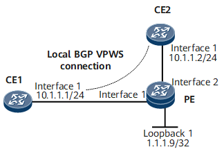
On the network shown in Figure 1, CE1 and CE2 connect to the same PE. A local BGP VPWS connection needs to be established between CE1 and CE2 for them to communicate. After the connection is established, the PE can function like a Layer 2 switch to directly transmit packets, without using any static LSP.

Configuration Roadmap
The configuration roadmap is as follows:
Enable basic MPLS functions and MPLS L2VPN on the PE.
Configure a local BGP VPWS connection between CE1 and CE2 on the PE.
Data Preparation
To complete the configuration, you need the following data:
L2VPN instance name
L2VPN instance RD
CE names and IDs
Procedure
- Configure CEs.
# Configure CE1.
<HUAWEI> system-view
[~HUAWEI] sysname CE1
[*HUAWEI] commit
[~CE1] interface gigabitethernet 0/1/0
[*CE1-GigabitEthernet0/1/0] ip address 10.1.1.1 24
[*CE1-GigabitEthernet0/1/0] quit
[*CE1] commit
# Configure CE2.
<HUAWEI> system-view
[~HUAWEI] sysname CE2
[*HUAWEI] commit
[~CE2] interface gigabitethernet 0/1/0
[*CE2-GigabitEthernet0/1/0] ip address 10.1.1.2 24
[*CE2-GigabitEthernet0/1/0] quit
[*CE2] commit
- Enable basic MPLS functions on the PE.
<HUAWEI> system-view
[~HUAWEI] sysname PE
[*HUAWEI] commit
[~PE] interface loopback 1
[*PE-LoopBack1] ip address 1.1.1.9 32
[*PE-LoopBack1] quit
[*PE] mpls lsr-id 1.1.1.9
[*PE] mpls
[*PE-mpls] quit
[*PE] commit
- Enable MPLS L2VPN and configure a local BGP VPWS connection on the PE.
[~PE] mpls l2vpn
[*PE-l2vpn] quit
[*PE] mpls l2vpn vpn1 encapsulation ethernet
[*PE-mpls-l2vpn-vpn1] route-distinguisher 100:1
[*PE-mpls-l2vpn-vpn1] ce ce1 id 1 range 10
[*PE-mpls-l2vpn-vpn1-ce-ce1] connection ce-offset 2 interface gigabitethernet 0/1/0
[*PE-mpls-l2vpn-vpn1-ce-ce1] quit
[*PE-mpls-l2vpn-vpn1] ce ce2 id 2 range 10
[*PE-mpls-l2vpn-vpn1-ce-ce2] connection ce-offset 1 interface gigabitethernet 0/1/8
[*PE-mpls-l2vpn-vpn1-ce-ce2] quit
[*PE-mpls-l2vpn-vpn1] quit
[*PE] commit
- Verify the configuration.
After completing the configuration, run the display mpls l2vpn connection command on the PE. The command output shows that two VPWS connections have been established and are in the Up state.
[~PE] display mpls l2vpn connection
2 total connections,
connections: 2 up, 0 down, 2 local, 0 remote, 0 unknown

VPN name: vpn1,
2 total connections,
connections: 2 up, 0 down , 2 local, 0 remote, 0 unknown

  CE name: ce1, id: 1,
  Rid type status peer-id         route-distinguisher interface
  primary or not
----------------------------------------------------------------------------
  2   loc  up     ---             ---                 GigabitEthernet0/1/0
  primary
  CE name: ce2, id: 2,
  Rid type status peer-id         route-distinguisher interface
  primary or not
----------------------------------------------------------------------------
  1   loc  up     ---             ---                 GigabitEthernet0/1/8
  primary
CE1 and CE2 can ping each other. The following example uses the command output on CE1.
[~CE1] ping 10.1.1.2
  PING 10.1.1.2: 56  data bytes, press CTRL_C to break
    Reply from 10.1.1.2: bytes=56 Sequence=1 ttl=255 time=7 ms
    Reply from 10.1.1.2: bytes=56 Sequence=2 ttl=255 time=3 ms
    Reply from 10.1.1.2: bytes=56 Sequence=3 ttl=255 time=4 ms
    Reply from 10.1.1.2: bytes=56 Sequence=4 ttl=255 time=2 ms
    Reply from 10.1.1.2: bytes=56 Sequence=5 ttl=255 time=3 ms

  --- 10.1.1.2 ping statistics ---
    5 packet(s) transmitted
    5 packet(s) received
    0.00% packet loss
    round-trip min/avg/max = 2/3/7 ms
Configuration Files
CE1 configuration file
#
sysname CE1
#
interface GigabitEthernet0/1/0
 undo shutdown
 ip address 10.1.1.1 255.255.255.0
#
return
CE2 configuration file
#
sysname CE2
#
interface GigabitEthernet0/1/0
 undo shutdown
 ip address 10.1.1.2 255.255.255.0
#
return
PE configuration file
#
sysname PE1
#
mpls lsr-id 1.1.1.9
#
mpls
#
mpls l2vpn
#
interface LoopBack1
 ip address 1.1.1.9 255.255.255.255
#
mpls l2vpn vpn1 encapsulation ethernet
 route-distinguisher 100:1
 ce ce1 id 1 range 10 default-offset 0
  connection ce-offset 2 interface GigabitEthernet0/1/0
 ce ce2 id 2 range 10 default-offset 0
  connection ce-offset 1 interface GigabitEthernet0/1/8
#
return