Example for Configuring a Remote BGP VPWS Connection
This section provides an example for configuring a remote BGP VPWS connection. If two CEs connect to different PEs, you can configure a remote BGP VPWS connection for the two CEs to communicate.
Networking Requirements
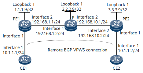
On the network shown in Figure 1, CE1 and CE2 connect to different PEs. A remote BGP VPWS connection needs to be established between PE1 and PE2 for the two CEs to communicate.

Configuration Roadmap
The configuration roadmap is as follows:
Configure a routing protocol on the PEs and P of the backbone network to ensure IP connectivity and configure basic MPLS functions and LDP.
Configure PEs to exchange VPWS information as BGP peers.
Enable MPLS L2VPN on PEs and create a remote BGP VPWS connection between them.
Data Preparation
To complete the configuration, you need the following data:
AS number
L2VPN instance name
L2VPN instance RD and VPN targets
CE names and IDs
Procedure
- Configure IP addresses.
# Configure CE1.
<HUAWEI> system-view
[~HUAWEI] sysname CE1
[*HUAWEI] commit
[~CE1] interface gigabitethernet 0/1/0
[*CE1-GigabitEthernet0/1/0] ip address 10.1.1.1 24
[*CE1-GigabitEthernet0/1/0] quit
[*CE1] commit
# Configure CE2.
<HUAWEI> system-view
[~HUAWEI] sysname CE2
[*HUAWEI] commit
[~CE2] interface gigabitethernet 0/1/0
[*CE2-GigabitEthernet0/1/0] ip address 10.1.1.2 24
[*CE2-GigabitEthernet0/1/0] quit
[*CE2] commit
# Configure PE1.
<HUAWEI> system-view
[~HUAWEI] sysname PE1
[*HUAWEI] commit
[~PE1] interface loopback 1
[*PE1-LoopBack1] ip address 1.1.1.9 32
[*PE1-LoopBack1] quit
[*PE1] interface gigabitethernet 0/1/8
[*PE1-GigabitEthernet0/1/8] ip address 192.168.1.1 24
[*PE1-GigabitEthernet0/1/8] quit
[*PE1] commit
# Configure the P.
<HUAWEI> system-view
[~HUAWEI] sysname P
[*HUAWEI] commit
[~P] interface loopback 1
[*P-LoopBack1] ip address 2.2.2.9 32
[*P-LoopBack1] quit
[*P] interface gigabitethernet 0/1/0
[*P-GigabitEthernet0/1/0] ip address 192.168.1.2 24
[*P-GigabitEthernet0/1/0] quit
[*P] interface gigabitethernet 0/1/8
[*P-GigabitEthernet0/1/8] ip address 192.168.10.1 24
[*P-GigabitEthernet0/1/8] quit
[*P] commit
# Configure PE2.
<HUAWEI> system-view
[~HUAWEI] sysname PE2
[*HUAWEI] commit
[*PE2] interface loopback 1
[*PE2-LoopBack1] ip address 3.3.3.9 24
[*PE2-LoopBack1] quit
[~PE2] interface gigabitethernet 0/1/8
[*PE2-GigabitEthernet0/1/8] ip address 192.168.10.2 24
[*PE2-GigabitEthernet0/1/8] quit
[*PE2] commit
- Configure an IGP. In this example, OSPF is used.
# Configure PE1.
[~PE1] ospf 1
[*PE1-ospf-1] area 0
[*PE1-ospf-1-area-0.0.0.0] network 1.1.1.9 0.0.0.0
[*PE1-ospf-1-area-0.0.0.0] network 192.168.1.0 0.0.0.255
[*PE1-ospf-1-area-0.0.0.0] quit
[*PE1-ospf-1] quit
[*PE1] commit
# Configure the P.
[~P] ospf 1
[*P-ospf-1] area 0
[*P-ospf-1-area-0.0.0.0] network 2.2.2.9 0.0.0.0
[*P-ospf-1-area-0.0.0.0] network 192.168.1.0 0.0.0.255
[*P-ospf-1-area-0.0.0.0] network 192.168.10.0 0.0.0.255
[*P-ospf-1-area-0.0.0.0] quit
[*P-ospf-1] quit
[*P] commit
# Configure PE2.
[~PE2] ospf 1
[*PE2-ospf-1] area 0
[*PE2-ospf-1-area-0.0.0.0] network 3.3.3.9 0.0.0.0
[*PE2-ospf-1-area-0.0.0.0] network 192.168.10.0 0.0.0.255
[*PE2-ospf-1-area-0.0.0.0] quit
[*PE2-ospf-1] quit
[*PE2] commit
- Configure basic MPLS functions and establish an LSP.
# Configure PE1.
[~PE1] mpls lsr-id 1.1.1.9
[*PE1] mpls
[*PE1-mpls] quit
[*PE1] mpls ldp
[*PE1-mpls-ldp] quit
[*PE1] interface gigabitethernet 0/1/8
[*PE1-GigabitEthernet0/1/8] mpls
[*PE1-GigabitEthernet0/1/8] mpls ldp
[*PE1-GigabitEthernet0/1/8] quit
[*PE1] commit
# Configure the P.
[~P] mpls lsr-id 2.2.2.9
[*P] mpls
[*P-mpls] quit
[*P] mpls ldp
[*P-mpls-ldp] quit
[*P] interface gigabitethernet 0/1/0
[*P-GigabitEthernet0/1/0] mpls
[*P-GigabitEthernet0/1/0] mpls ldp
[*PE1-GigabitEthernet0/1/0] quit
[*P] interface gigabitethernet 0/1/8
[*P-GigabitEthernet0/1/8] mpls
[*P-GigabitEthernet0/1/8] mpls ldp
[*P-GigabitEthernet0/1/8] quit
[*P] commit
# Configure PE2.
[~PE1] mpls lsr-id 3.3.3.9
[*PE1] mpls
[*PE1-mpls] quit
[*PE1] mpls ldp
[*PE1-mpls-ldp] quit
[*PE1] interface gigabitethernet 0/1/8
[*PE1-GigabitEthernet0/1/8] mpls
[*PE1-GigabitEthernet0/1/8] mpls ldp
[*PE1-GigabitEthernet0/1/8] quit
[*PE1] commit
- Configure PEs to exchange VPWS information as BGP peers.
# Configure PE1.
[~PE1] bgp 100
[*PE1-bgp] peer 3.3.3.9 as-number 100
[*PE1-bgp] peer 3.3.3.9 connect-interface loopback 1
[*PE1-bgp] l2vpn-ad-family
[*PE1-bgp-af-l2vpn-ad] peer 3.3.3.9 enable
[*PE1-bgp-af-l2vpn-ad] peer 3.3.3.9 signaling vpws
[*PE1-bgp-af-l2vpn-ad] quit
[*PE1-bgp] quit
[*PE1] commit
# Configure PE2.
[~PE2] bgp 100
[*PE2-bgp] peer 1.1.1.9 as-number 100
[*PE2-bgp] peer 1.1.1.9 connect-interface loopback 1
[*PE2-bgp] l2vpn-ad-family
[*PE2-bgp-af-l2vpn-ad] peer 1.1.1.9 enable
[*PE2-bgp-af-l2vpn-ad] peer 1.1.1.9 signaling vpws
[*PE2-bgp-af-l2vpn-ad] quit
[*PE2-bgp] quit
[*PE2] commit
- Configure a remote BGP VPWS connection.
# Configure PE1.
[~PE1] mpls l2vpn
[*PE1-l2vpn] quit
[*PE1] mpls l2vpn vpn1 encapsulation ethernet
[*PE1-mpls-l2vpn-vpn1] route-distinguisher 100:1
[*PE1-mpls-l2vpn-vpn1] vpn-target 200:1 both
[*PE1-mpls-l2vpn-vpn1] ce ce1 id 1 range 10
[*PE1-mpls-l2vpn-vpn1-ce-ce1] connection ce-offset 2 interface gigabitethernet 0/1/0
[*PE1-mpls-l2vpn-vpn1-ce-ce1] quit
[*PE1] commit
# Configure PE2.
[~PE2] mpls l2vpn
[*PE2-l2vpn] quit
[*PE2] mpls l2vpn vpn1 encapsulation ethernet
[*PE2-mpls-l2vpn-vpn1] route-distinguisher 100:1
[*PE2-mpls-l2vpn-vpn1] vpn-target 200:1 both
[*PE2-mpls-l2vpn-vpn1] ce ce2 id 2 range 10
[*PE2-mpls-l2vpn-vpn1-ce-ce2] connection ce-offset 1 interface gigabitethernet 0/1/0
[*PE2-mpls-l2vpn-vpn1-ce-ce2] quit
[*PE2-mpls-l2vpn-vpn1] quit
[*PE2] commit
- Verify the configuration.
After completing the configuration, run the display mpls l2vpn connection command on each PE. The command output shows that a VPWS connection has been established and is in the Up state. The following example uses the command output on PE1.
[~PE1] display mpls l2vpn connection
1 total connections,
connections: 1 up, 0 down, 0 local, 1 remote, 0 unknown

VPN name: vpn1,
1 total connections,
connections: 1 up, 0 down , 0 local, 1 remote, 0 unknown

  CE name: ce1, id: 1,
  Rid type status peer-id         route-distinguisher interface
  primary or not
----------------------------------------------------------------------------
  2   rmt  up     3.3.3.9         100:1               GigabitEthernet0/1/0
  primary
CE1 and CE2 can ping each other. The following example uses the command output on CE1.
[~CE1] ping 10.1.1.2
  PING 10.1.1.2: 56  data bytes, press CTRL_C to break
    Reply from 10.1.1.2: bytes=56 Sequence=1 ttl=255 time=7 ms
    Reply from 10.1.1.2: bytes=56 Sequence=2 ttl=255 time=3 ms
    Reply from 10.1.1.2: bytes=56 Sequence=3 ttl=255 time=4 ms
    Reply from 10.1.1.2: bytes=56 Sequence=4 ttl=255 time=2 ms
    Reply from 10.1.1.2: bytes=56 Sequence=5 ttl=255 time=3 ms

  --- 10.1.1.2 ping statistics ---
    5 packet(s) transmitted
    5 packet(s) received
    0.00% packet loss
    round-trip min/avg/max = 2/3/7 ms
Configuration Files
CE1 configuration file
#
sysname CE1
#
interface GigabitEthernet0/1/0
 undo shutdown
 ip address 10.1.1.1 255.255.255.0
#
return
CE2 configuration file
#
sysname CE2
#
interface GigabitEthernet0/1/0
 undo shutdown
 ip address 10.1.1.2 255.255.255.0
#
return
PE1 configuration file
#
sysname PE1
#
mpls lsr-id 1.1.1.9
#
mpls
#
mpls l2vpn
#
mpls ldp
#
interface GigabitEthernet0/1/0
 undo shutdown
#
interface GigabitEthernet0/1/8
 undo shutdown
 ip address 192.168.1.1 255.255.255.0
 mpls
 mpls ldp
#
interface LoopBack1
 ip address 1.1.1.9 255.255.255.255
#
mpls l2vpn vpn1 encapsulation ethernet
 route-distinguisher 100:1
 vpn-target 200:1 import-extcommunity
 vpn-target 200:1 export-extcommunity
 ce ce1 id 1 range 10 default-offset 0
  connection ce-offset 2 interface GigabitEthernet0/1/0
#
bgp 100
 peer 3.3.3.9 as-number 100
 peer 3.3.3.9 connect-interface LoopBack1
 #
 ipv4-family unicast
  undo synchronization
  peer 3.3.3.9 enable
 #
 l2vpn-ad-family
  policy vpn-target
  peer 3.3.3.9 enable
  peer 3.3.3.9 signaling vpws
#
ospf 1
 area 0.0.0.0
  network 1.1.1.9 0.0.0.0
  network 192.168.1.0 0.0.0.255
#
return
P configuration file
#
sysname P
#
mpls lsr-id 2.2.2.9
#
mpls
#
mpls ldp
#
interface GigabitEthernet0/1/0
 undo shutdown
 ip address 192.168.1.2 255.255.255.0
 mpls
 mpls ldp
#
interface GigabitEthernet0/1/8
 undo shutdown
 ip address 192.168.10.1 255.255.255.0
 mpls
 mpls ldp
#
interface LoopBack1
 ip address 2.2.2.9 255.255.255.255
#
ospf 1
 area 0.0.0.0
  network 2.2.2.9 0.0.0.0
  network 192.168.1.0 0.0.0.255
  network 192.168.10.0 0.0.0.255
#
return
PE2 configuration file
#
sysname PE2
#
mpls lsr-id 3.3.3.9
#
mpls
#
mpls l2vpn
#
mpls ldp
#
interface GigabitEthernet0/1/0
 undo shutdown
#
interface GigabitEthernet0/1/8
 undo shutdown
 ip address 192.168.10.2 255.255.255.0
 mpls
 mpls ldp
#
interface LoopBack1
 ip address 3.3.3.9 255.255.255.255
#
mpls l2vpn vpn1 encapsulation ethernet
 route-distinguisher 100:1
 vpn-target 200:1 import-extcommunity
 vpn-target 200:1 export-extcommunity
 ce ce2 id 2 range 10 default-offset 0
  connection ce-offset 1 interface GigabitEthernet0/1/0
#
bgp 100
 peer 1.1.1.9 as-number 100
 peer 1.1.1.9 connect-interface LoopBack1
 #
 ipv4-family unicast
  undo synchronization
  peer 1.1.1.9 enable
 #
 l2vpn-ad-family
  policy vpn-target
  peer 1.1.1.9 enable
  peer 1.1.1.9 signaling vpws
#
ospf 1
 area 0.0.0.0
  network 3.3.3.9 0.0.0.0
  network 192.168.10.0 0.0.0.255
#
return