Establishment of a Three-Segment VXLAN for Layer 3 Communication Between DCs
Background
To meet the requirements of inter-regional operations, user access, geographical redundancy, and other scenarios, an increasing number of enterprises deploy DCs across regions. Data Center Interconnect (DCI) is a solution that enables communication between VMs in different DCs. Using technologies such as VXLAN and BGP EVPN, DCI securely and reliably transmits DC packets over carrier networks. Three-segment VXLAN can be configured to enable inter-subnet communication between VMs in different DCs.
Benefits
Three-segment VXLAN enables Layer 3 communication between DC and offers the following benefits to users:
- Hosts in different DCs can communicate at Layer 3.
- Different DCs do not need to run the same routing protocol for communication.
- Different DCs do not require information orchestration for communication.
Implementation
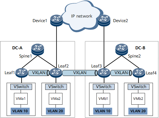
Three-segment VXLAN establishes one VXLAN tunnel segment in each of the DCs and also establishes one VXLAN tunnel segment between the DCs. As shown in Figure 1, BGP EVPN is used to create VXLAN tunnels in distributed gateway mode within both DC A and DC B so that the VMs in each DC can communicate with each other. Leaf2 and Leaf3 are the edge devices within the DCs that connect to the backbone network. BGP EVPN is used to configure a VXLAN tunnel between Leaf2 and Leaf3, so that the VXLAN packets received by one DC can be decapsulated, re-encapsulated, and sent to the peer DC. This process provides E2E transport for inter-DC VXLAN packets and ensures that VMs in different DCs can communicate with each other.

This function applies only to IPv4 over IPv4 networks.
In three-segment VXLAN scenarios, only VXLAN tunnels in distributed gateway mode can be deployed in DCs.
Control Plane
The following describes how three-segment VXLAN tunnels are established.
The process of advertising routes on Leaf1 and Leaf4 is not described in this section. For details, see VXLAN Tunnel Establishment.
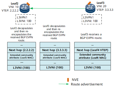
- Leaf4 learns the IP address of VMb2 in DC B and saves it to the routing table for the L3VPN instance. Leaf4 then sends a BGP EVPN route to Leaf3.
- As shown in Figure 2, Leaf3 receives the BGP EVPN route and obtains the host IP route contained in it. Leaf3 then establishes a VXLAN tunnel to Leaf 4 according to the process described in VXLAN Tunnel Establishment. Leaf3 sets the next hop of the route to its own VTEP address, re-encapsulates the route with the Layer 3 VNI of the L3VPN instance, and sets the source MAC address of the route to its own MAC address. Finally, Leaf3 sends the re-encapsulated BGP EVPN route to Leaf2.
- Leaf2 receives the BGP EVPN route and obtains the host IP route contained in it. Leaf2 then establishes a VXLAN tunnel to Leaf3 according to the process described in VXLAN Tunnel Establishment. Leaf2 sets the next hop of the route to its own VTEP address, re-encapsulates the route with the Layer 3 VNI of the L3VPN instance, and sets the source MAC address of the route to its own MAC address. Finally, Leaf2 sends the re-encapsulated BGP EVPN route to Leaf1.
- Leaf1 receives the BGP EVPN route and establishes a VXLAN tunnel to Leaf2 according to the process described in VXLAN Tunnel Establishment.
Data Packet Forwarding
A general overview of the packet forwarding process on Leaf1 and Leaf4 is provided below. For detailed information, see Intra-subnet Packet Forwarding.
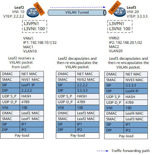
- Leaf1 receives Layer 2 packets destined for VMb2 from VMa1 and determines that the destination MAC addresses in these packets are all gateway interface MAC addresses. Leaf1 then terminates these Layer 2 packets and finds the L3VPN instance corresponding to the BDIF interface through which VMa1 accesses the broadcast domain. Leaf1 then searches the L3VPN instance routing table for the VMb2 host route, encapsulates the received packets as VXLAN packets, and sends them to Leaf2 over the VXLAN tunnel.
- As shown in Figure 3, Leaf2 receives and parses these VXLAN packets. After finding the L3VPN instance corresponding to the Layer 3 VNI of the packets, Leaf2 searches the L3VPN instance routing table for the VMb2 host route. Leaf2 then re-encapsulates these VXLAN packets (setting the Layer 3 VNI and inner destination MAC address to the Layer 3 VNI and MAC address carried in the VMb2 host route sent by Leaf3). Finally, Leaf2 sends these packets to Leaf3.
- As shown in Figure 3, Leaf3 receives and parses these VXLAN packets. After finding the L3VPN instance corresponding to the Layer 3 VNI of the packets, Leaf3 searches the L3VPN instance routing table for the VMb2 host route. Leaf3 then re-encapsulates these VXLAN packets (setting the Layer 3 VNI and inner destination MAC address to the Layer 3 VNI and MAC address carried in the VMb2 host route sent by Leaf4). Finally, Leaf3 sends these packets to Leaf4.
- Leaf4 receives and parses these VXLAN packets. After finding the L3VPN instance corresponding to the Layer 3 VNI of the packets, Leaf4 searches the L3VPN instance routing table for the VMb2 host route. Using this routing information, Leaf4 forwards these packets to VMb2.
Other Functions
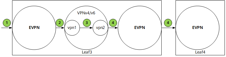
Local leaking of EVPN routes is needed in scenarios where different VPN instances are used for the access of different services in a DC and but an external VPN instance is used to communicate with other DCs to block VPN instance allocation information within the DC from the outside. Depending on route sources, this function can be used in the following scenarios:
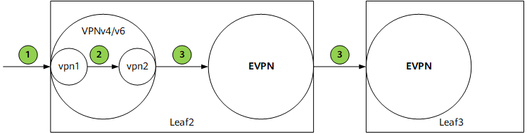
Local VPN routes are advertised through EVPN after being locally leaked
- The function to import VPN routes to a local VPN instance named vpn1 is configured in the BGP VPN instance IPv4 or IPv6 address family.
- vpn1 sends received routes to the VPNv4 or VPNv6 component, which then checks whether the ERT of vpn1 is the same as the IRT of the external VPN instance vpn2. If they are the same, the VPNv4 or VPNv6 component imports these routes to vpn2.
- vpn2 sends locally leaked routes to the EVPN component and advertises these routes as BGP EVPN routes to peers. In this case, vpn2 must be able to advertise locally leaked routes as BGP EVPN routes.
Remote public network routes are advertised through EVPN after being locally leaked
- The EVPN component receives public network routes from a remote peer.
- The EVPN component imports the received routes to vpn1.
- vpn1 sends received routes to the VPNv4 or VPNv6 component, which then checks whether the ERT of vpn1 is the same as the IRT of vpn2. If they are the same, the VPNv4 or VPNv6 component imports these routes to vpn2. In this case, vpn1 must be able to perform remote and local route leaking route leaking in succession.
- vpn2 sends locally leaked routes to the EVPN component and advertises these routes as BGP EVPN routes to peers. In this case, vpn2 must be able to advertise locally leaked routes as BGP EVPN routes.