Using Three-Segment VXLAN to Implement Layer 2 Interconnection Between DCs
Background
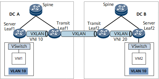
Figure 1 shows the scenario where three-segment VXLAN is deployed to implement Layer 2 interconnection between DCs. VXLAN tunnels are configured both within DC A and DC B and between transit leaf nodes in both DCs. To enable communication between VM1 and VM2, implement Layer 2 communication between DC A and DC B. If the VXLAN tunnels within DC A and DC B use the same VXLAN Network Identifier (VNI), this VNI can also be used to establish a VXLAN tunnel between Transit Leaf1 and Transit Leaf2. In practice, however, different DCs have their own VNI spaces. Therefore, the VXLAN tunnels within DC A and DC B tend to use different VNIs. In this case, to establish a VXLAN tunnel between Transit Leaf1 and Transit Leaf2, VNIs conversion must be implemented.
Benefits
This solution offers the following benefits to users:
Implements Layer 2 interconnection between hosts in different DCs.
Decouples the VNI space of the network within a DC from that of the network between DCs, simplifying network maintenance.
Isolates network faults within a DC from those between DCs, facilitating fault location.
Principles
Currently, this solution is implemented in the local VNI mode. It is similar to downstream label allocation. The local VNI of the peer transit leaf node functions as the outbound VNI, which is used by packets that the local transit leaf node sends to the peer transit leaf node for VXLAN encapsulation.
Control Plane

This function is only supported for IPv4 over IPv4 networks.
The establishment of VXLAN tunnels between leaf nodes is the same as VXLAN tunnel establishment for intra-subnet interworking in common VXLAN scenarios. Therefore, the detailed process is not described here. Regarding the control plane, MAC address learning by a host is described here.
On the network shown in Figure 2, the control plane is implemented as follows:
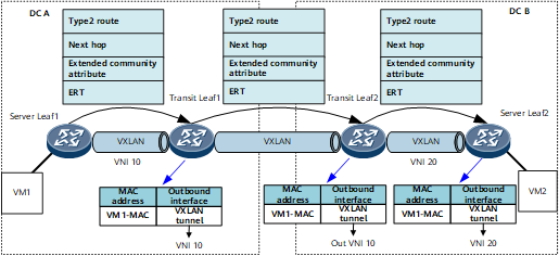
Server Leaf1 learns VM1's MAC address, generates a BGP EVPN route, and sends it to Transit Leaf1. The BGP EVPN route contains the following information:
Type 2 route: EVPN instance's RD value, VM1's MAC address, and Server Leaf1's local VNI.
Next hop: Server Leaf1's VTEP IP address.
Extended community attribute: encapsulated tunnel type (VXLAN).
ERT: EVPN instance's export RT value.
Upon receipt, Transit Leaf1 adds the BGP EVPN route to its local EVPN instance and generates a MAC address entry for VM1 in the EVPN instance-bound BD. Based on the next hop and encapsulated tunnel type, the MAC address entry's outbound interface recurses to the VXLAN tunnel destined for Server Leaf1. The VNI in VXLAN tunnel encapsulation information is Transit Leaf1's local VNI.
Transit Leaf1 re-originates the BGP EVPN route and then advertises the route to Transit Leaf2. The re-originated BGP EVPN route contains the following information:
Type 2 route: EVPN instance's RD value, VM1's MAC address, and Transit Leaf1's local VNI.
Next hop: Transit Leaf1's VTEP IP address.
Extended community attribute: encapsulated tunnel type (VXLAN).
ERT: EVPN instance's export RT value.
Upon receipt, Transit Leaf2 adds the re-originated BGP EVPN route to its local EVPN instance and generates a MAC address entry for VM1 in the EVPN instance-bound BD. Based on the next hop and encapsulated tunnel type, the MAC address entry's outbound interface recurses to the VXLAN tunnel destined for Transit Leaf1. The outbound VNI in VXLAN tunnel encapsulation information is Transit Leaf1's local VNI.
Transit Leaf2 re-originates the BGP EVPN route and then advertises the route to Server Leaf2. The re-originated BGP EVPN route contains the following information:
Type 2 route: EVPN instance's RD value, VM1's MAC address, and Transit Leaf2's local VNI.
Next hop: Transit Leaf2's VTEP IP address.
Extended community attribute: encapsulated tunnel type (VXLAN).
ERT: EVPN instance's export RT value.
Upon receipt, Server Leaf2 adds the re-originated BGP EVPN route to its local EVPN instance and generates a MAC address entry for VM1 in the EVPN instance-bound BD. Based on the next hop and encapsulated tunnel type, the MAC address entry's outbound interface recurses to the VXLAN tunnel destined for Transit Leaf2. The VNI in VXLAN tunnel encapsulation information is Server Leaf2's local VNI.
The preceding process takes MAC address learning by VM1 for example. MAC address learning by VM2 is the same, which is not described here.
Forwarding Plane
Figure 3 shows the known unicast packets are forwarded. The following example process shows how VM2 sends Layer 2 packets to VM1:
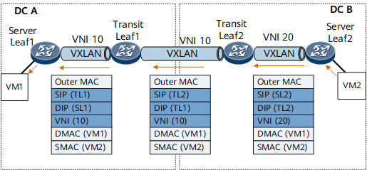
After receiving a Layer 2 packet from VM2 through a BD Layer 2 sub-interface, Server Leaf2 searches the BD's MAC address table based on the destination MAC address for the VXLAN tunnel's outbound interface and obtains VXLAN tunnel encapsulation information (local VNI, destination VTEP IP address, and source VTEP IP address). Based on the obtained information, the Layer 2 packet is encapsulated through the VXLAN tunnel and then forwarded to Transit Leaf2.
Upon receipt, Transit Leaf2 decapsulates the VXLAN packet, finds the target BD based on the VNI, searches the BD's MAC address table based on the destination MAC address for the VXLAN tunnel's outbound interface, and obtains the VXLAN tunnel encapsulation information (outbound VNI, destination VTEP IP address, and source VTEP IP address). Based on the obtained information, the Layer 2 packet is encapsulated through the VXLAN tunnel and then forwarded to Transit Leaf1.
Upon receipt, Transit Leaf1 decapsulates the VXLAN packet. Because the packet's VNI is Transit Leaf1's local VNI, the target BD can be found based on this VNI. Transit Leaf1 also searches the BD's MAC address table based on the destination MAC address for the VXLAN tunnel's outbound interface and obtains the VXLAN tunnel encapsulation information (local VNI, destination VTEP IP address, and source VTEP IP address). Based on the obtained information, the Layer 2 packet is encapsulated through the VXLAN tunnel and then forwarded to Server Leaf1.
Upon receipt, Server Leaf1 decapsulates the VXLAN packet and forwards it at Layer 2 to VM1.
In the scenario with three-segment VXLAN for Layer 2 interworking, BUM packet forwarding is the same as that in the common VXLAN scenario except that the split horizon group is used to prevent loops. The similarities are not described here.
After receiving BUM packets from a Server Leaf node in the same DC, a Transit Leaf node obtains the split horizon group to which the source VTEP belongs. Because all nodes in the same DC belong to the default split horizon group, BUM packets will not be replicated to other Server Leaf nodes within the DC. Because the peer Transit Leaf node belongs to a different split horizon group, BUM packets will be replicated to the peer Transit Leaf node.
Upon receipt, the peer Transit Leaf node obtains the split horizon group to which the source VTEP belongs. Because the Transit Leaf nodes at both ends belong to the same split horizon group, BUM packets will not be replicated to the peer Transit Leaf node. Because the Server Leaf nodes within the DC belong to a different split horizon group, BUM packets will be replicated to them.