I-PMSI Tunnel Establishment
- RSVP-TE P2MP tunnels: A sender PE sends an intra-AS PMSI A-D route to each receiver PE. Upon receipt, each receiver PE sends a reply message. Then, the sender PE collects P2MP tunnel leaf information from received reply messages and establishes an RSVP-TE P2MP tunnel for each MVPN based on the leaf information of the MVPN. For more information about RSVP-TE P2MP tunnel establishment, see "P2MP TE" in NetEngine 8000 F Feature Description - MPLS.
- mLDP P2MP tunnels: Receiver PEs directly send Label Mapping messages based on the root node address (sender PE address) and opaque value information carried in the Intra-AS PMSI A-D route sent by the sender PE to establish an mLDP P2MP tunnel. For more information about mLDP P2MP tunnel establishment, see "mLDP" in NetEngine 8000 F Feature Description - MPLS.

For comparison between RSVP-TE and mLDP P2MP tunnels, see Table 1 in NG MVPN Public Network Tunnel Principle.
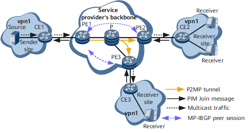
The following example uses the network shown in Figure 1 to describe how to establish PMSI tunnels. Because RSVP-TE P2MP tunnels and mLDP P2MP tunnels are established differently, the following uses two scenarios, RSVP-TE P2MP Tunnel and mLDP P2MP Tunnel, to describe how to establish PMSI tunnels.
This example presumes that:
- PE1 has established BGP MVPN peer relationships with PE2 and PE3, but no BGP MVPN peer relationship is established between PE2 and PE3.
- The network administrator has configured MVPN on PE1, PE2, and PE3 in turn.
RSVP-TE P2MP Tunnel
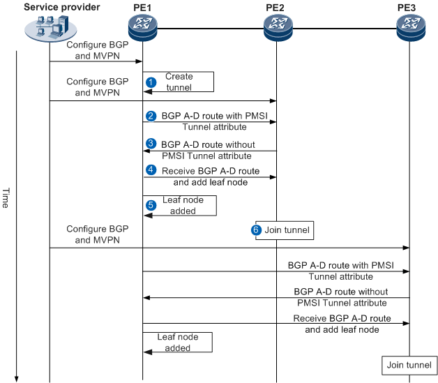
Figure 2 shows the time sequence for establishing an I-PMSI tunnel with the P-tunnel type as RSVP-TE P2MP LSP.
Table 1 briefs the procedure for establishing an I-PMSI tunnel with the P-tunnel type as RSVP-TE P2MP LSP.
Step |
Device |
Prerequisites |
Key Action |
|---|---|---|---|
 |
PE1 |
BGP and MVPN have been configured on PE1. PE1 has been configured as a sender PE. The P-tunnel type for I-PMSI tunnel establishment has been specified as RSVP-TE P2MP LSP. |
As a sender PE, PE1 initiates the I-PMSI tunnel establishment process. The MPLS module on PE1 reserves resources for the corresponding RSVP-TE P2MP tunnel. Because PE1 does not know RSVP-TE P2MP tunnel leaf information, the RSVP-TE P2MP tunnel is not established in a real sense. |
 |
PE1 |
BGP and MVPN have been configured on PE2. PE1 has established a BGP MVPN peer relationship with PE2. |
PE1 sends a Type 1 BGP A-D route to PE2. This route carries
the following information:
|
 |
PE2 |
- |
|
 |
PE1 |
- |
After PE1 receives the BGP A-D route from PE2, PE1 matches the export MVPN target of the route against its local import MVPN target. If the two targets match, PE1 accepts this route, records PE2 as an MVPN member, and instructs the MPLS module to send an MPLS message to PE2 and add PE2 as a leaf node of the RSVP-TE P2MP tunnel to be established. |
 |
PE1 |
- |
After PE1 receives a reply from PE2, the MPLS module on PE1 completes the process of establishing an RSVP-TE P2MP tunnel with PE1 as the root node and PE2 as a leaf node. For more information about RSVP-TE P2MP tunnel establishment, see "P2MP TE" in NetEngine 8000 F Feature Description - MPLS. |
 |
PE2 |
- |
After PE2 receives the MPLS message from PE1, PE2 joins the established RSVP-TE P2MP tunnel. |
PE3 joins the RSVP-TE P2MP tunnel rooted at PE1 in a similar way as PE2. After PE2 and PE3 both join the RSVP-TE P2MP tunnel rooted at PE1, the I-PMSI tunnel is established and the MVPN service becomes available.
mLDP P2MP Tunnel
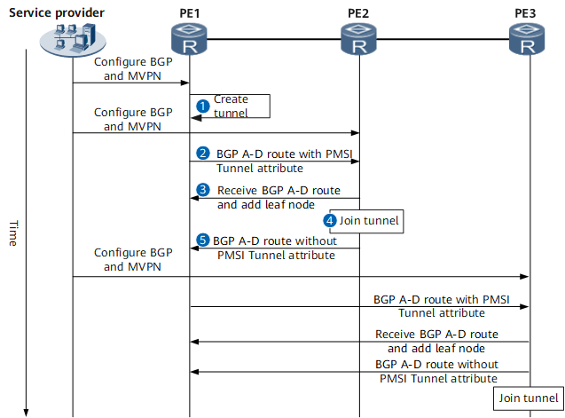
Figure 3 shows the time sequence for establishing an I-PMSI tunnel with the P-tunnel type as mLDP LSP.
Table 2 briefs the procedure for establishing an I-PMSI tunnel with the P-tunnel type as mLDP P2MP LSP.
Step |
Device |
Prerequisites |
Key Action |
|---|---|---|---|
 |
PE1 |
BGP and MVPN have been configured on PE1. PE1 has been configured as a sender PE. The P-tunnel type for I-PMSI tunnel establishment has been specified as mLDP P2MP LSP. |
As a sender PE, PE1 initiates the I-PMSI tunnel establishment process. The MPLS module on PE1 reserves resources (FEC information such as the opaque value and root node address) for the corresponding mLDP P2MP tunnel. Because PE1 does not know leaf information of the mLDP P2MP tunnel, the mLDP P2MP tunnel is not established in a real sense. |
 |
PE1 |
BGP and MVPN have been configured on PE2. PE1 has established a BGP MVPN peer relationship with PE2. |
PE1 sends a Type 1 BGP A-D route to PE2. This route carries
the following information:
|
 |
PE2 |
- |
After PE2 receives the BGP A-D route from PE1, the MPLS module on PE2 sends a Label Mapping message to PE1. This is because the PMSI Tunnel attribute carried in the received route specifies the P-tunnel type as mLDP, meaning that the P2MP tunnel must be established from leaves. After PE2 receives the MPLS message replied by PE1, PE2 becomes aware that the P2MP tunnel has been established. For more information about mLDP P2MP tunnel establishment, see "mLDP" in NetEngine 8000 F Feature Description - MPLS. |
 |
PE2 |
- |
PE2 creates an mLDP P2MP tunnel rooted at PE1. |
 |
PE2 |
- |
PE2 sends a BGP A-D route that carries the export MVPN target to PE1. Because PE2 is not a sender PE configured with PMSI tunnel information, the BGP A-D route sent by PE2 does not carry the PMSI Tunnel attribute. After PE1 receives the BGP A-D route from PE2, PE1 matches the export MVPN target of the route against its local import MVPN target. If the two targets match, PE1 accepts this route and records PE2 as an MVPN member. |
PE3 joins the mLDP P2MP tunnel and MVPN in a similar way as PE2. After PE2 and PE3 both join the mLDP P2MP tunnel rooted at PE1, the I-PMSI tunnel is established and the MVPN service becomes available.


