Switching Between I-PMSI and S-PMSI Tunnels
Background
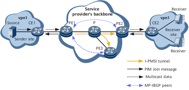
An NG MVPN uses the I-PMSI tunnel to send multicast data to receivers. The I-PMSI tunnel connects to all PEs on the MVPN and sends multicast data to these PEs regardless of whether these PEs have receivers. If some PEs do not have receivers, this implementation will cause redundant traffic, wasting bandwidth resources and increasing PEs' burdens.
To solve this problem, S-PMSI tunnels are introduced. An S-PMSI tunnel connects to the sender and receiver PEs of specific multicast sources and groups on an NG MVPN. Compared with the I-PMSI tunnel, an S-PMSI tunnel sends multicast data only to PEs interested in the data, reducing bandwidth consumption and PEs' burdens.

For comparison between I-PMSI and S-PMSI tunnels, see NG MVPN Public Network Tunnel Principle in Table 2.
Implementation
The following example uses the network shown in Figure 1 to describe switching between I-PMSI and S-PMSI tunnels on an NG MVPN.
Item |
Occurring Condition |
Description |
|---|---|---|
| Switching from the I-PMSI tunnel to an S-PMSI tunnel | The multicast data forwarding rate is consistently above the specified switching threshold. |
S-PMSI tunnels are classified as RSVP-TE S-PMSI tunnels
or mLDP S-PMSI tunnels, depending on the bearer tunnel type. For details
about switching from the I-PMSI tunnel to an S-PMSI tunnel, see:
|
| Switching from an S-PMSI tunnel to the I-PMSI tunnel | The multicast data forwarding rate is consistently below the specified switching threshold. |
- |
- After multicast data is switched from the I-PMSI tunnel to an S-PMSI tunnel, if the S-PMSI tunnel fails but the I-PMSI tunnel is still available, multicast data will be switched back to the I-PMSI tunnel.
- After multicast data is switched from the I-PMSI tunnel to an S-PMSI tunnel, if the multicast data forwarding rate is consistently below the specified switching threshold but the I-PMSI tunnel is unavailable, multicast data still travels along the S-PMSI tunnel.
Switching from the I-PMSI Tunnel to an S-PMSI Tunnel
Switching from the I-PMSI Tunnel to an RSVP-TE S-PMSI Tunnel
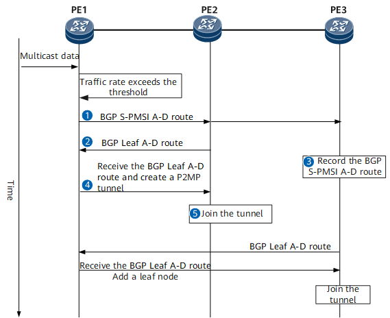
Figure 2 shows the time sequence for switching from the I-PMSI tunnel to an RSVP-TE S-PMSI tunnel. Table 2 describes the specific switching procedure.
Table 2 Procedure for switching from the I-PMSI tunnel to an RSVP-TE S-PMSI tunnel Step
Device
Key Action

PE1
After PE1 detects that the multicast data forwarding rate exceeds the specified switching threshold, PE1 initiates switching from the I-PMSI tunnel to an S-PMSI tunnel by sending a BGP S-PMSI A-D route to its BGP peers. In the BGP S-PMSI A-D route, the Leaf Information Require flag is set to 1, indicating that a PE that receives this route needs to send a BGP Leaf A-D route in response if the PE wants to join the S-PMSI tunnel to be established.

PE2
Upon receipt of the BGP S-PMSI A-D route, PE2, which has downstream receivers, sends a BGP Leaf A-D route to PE1.

PE3
Upon receipt of the BGP S-PMSI A-D route, PE3, which does not have downstream receivers, does not send a BGP Leaf A-D route to PE1 but records the BGP S-PMSI A-D route information.

PE1
Upon receipt of the BGP Leaf A-D route from PE2, PE1 establishes an S-PMSI tunnel with itself as the root node and PE2 as a leaf node.

PE2
After PE2 detects that the RSVP-TE S-PMSI tunnel has been established, PE2 joins this tunnel.
After PE3 has downstream receivers, PE3 will send a BGP Leaf A-D route to PE1. Upon receipt of the route, PE1 adds PE3 as a leaf node of the RSVE-TE S-PMSI tunnel. After PE3 joins the tunnel, PE3's downstream receivers will also be able to receive multicast data.
Switching from the I-PMSI Tunnel to an mLDP S-PMSI Tunnel
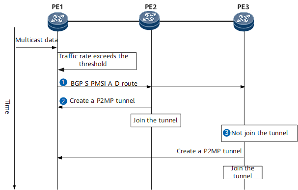
Figure 3 shows the time sequence for switching from the I-PMSI tunnel to an mLDP S-PMSI tunnel. Table 3 describes the specific switching procedure.
Table 3 Procedure for switching from the I-PMSI tunnel to an mLDP S-PMSI tunnel Step
Device
Key Action
PE1
After PE1 detects that the multicast data forwarding rate exceeds the specified switching threshold, PE1 initiates switching from the I-PMSI tunnel to an S-PMSI tunnel by sending a BGP S-PMSI A-D route to its BGP peers. In the BGP S-PMSI A-D route, the Leaf Information Require flag is set to 0.
PE2
Upon receipt of the BGP S-PMSI A-D route, PE2, which has downstream receivers, directly joins the mLDP S-PMSI tunnel specified in the BGP S-PMSI A-D route.
PE3
Upon receipt of the BGP S-PMSI A-D route, PE3, which does not have downstream receivers, does not join the mLDP S-PMSI tunnel specified in the BGP S-PMSI A-D route, but records the BGP S-PMSI A-D route information.
After PE3 has downstream receivers, PE3 will also directly join the mLDP S-PMSI tunnel. Then, PE3's downstream receivers will also be able to receive multicast data.
PE1 starts a switch-delay timer upon the completion of S-PMSI tunnel establishment and determines whether to switch multicast data to the S-PMSI tunnel as follows: If the S-PMSI tunnel fails to be established, PE1 still uses the I-PMSI tunnel to send multicast data. If the multicast data forwarding rate is consistently below the specified switching threshold throughout the timer lifecycle, PE1 still uses the I-PMSI tunnel to transmit multicast data. If the multicast data forwarding rate is consistently above the specified switching threshold throughout the timer lifecycle, PE1 switches data to the S-PMSI tunnel for transmission.
Switching from an S-PMSI Tunnel to the I-PMSI Tunnel
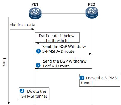
Figure 4 shows the time sequence for switching from an S-PMSI tunnel to the I-PMSI tunnel. Table 4 describes the specific switching procedure.
Step |
Device |
Key Action |
|---|---|---|
|
PE1 |
After PE1 detects that the multicast data forwarding rate
is consistently below the specified switching threshold, PE1 starts
a switchback hold timer:
|
|
PE2 |
Upon receipt of the BGP Withdraw S-PMSI A-D route, PE2 withdraws the bindings between its multicast entries and the S-PMSI tunnel. If PE2 has sent a BGP Leaf A-D route to PE1, PE2 will send a BGP Withdraw Leaf A-D route to PE1 in this step. |
|
PE2 |
After PE2 detects that none of its multicast entries is bound to the S-PMSI tunnel, PE2 leaves the S-PMSI tunnel. |
|
PE1 |
PE1 deletes the S-PMSI tunnel after waiting for a specified period of time. |
- Before the timer expires, leaf PEs delete tunnel protection groups to skip the status check of the primary I-PMSI or S-PMSI tunnel. The leaf PEs select the multicast data received from the primary tunnel and discard the multicast data received from the backup tunnel.
- After the timer expires, leaf PEs start to check the primary I-PMSI or S-PMSI tunnel status again. Leaf PEs select the multicast data received from the primary tunnel only if the primary tunnel is Up. If the primary tunnel is Down, Leaf PEs select the multicast data received from the backup tunnel.