Basic Functions
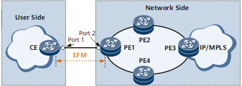
EFM supports OAM discovery, link monitoring, fault notification, and remote loopback. The following example illustrates EFM implementation on the network shown in Figure 1. The customer edge (CE) is a device in a customer equipment room, and provider edge 1 (PE1) is a carrier device. EFM is used to monitor the link connecting the CE to PE1, allowing the carrier to remotely manage link connectivity and quality.
OAM Discovery
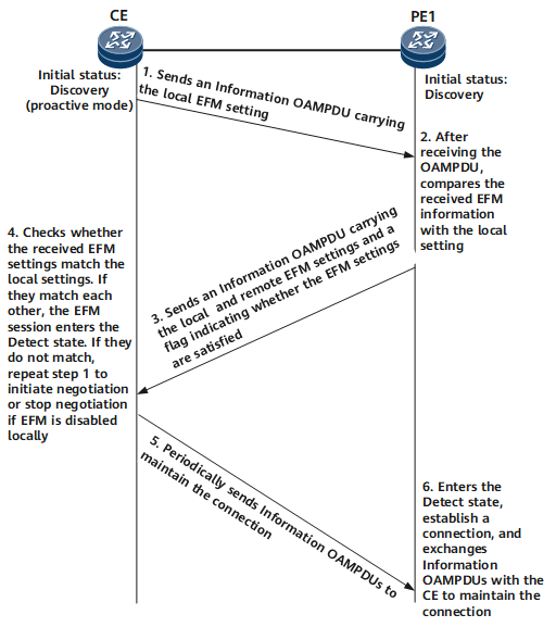
EFM entities at both ends of an EFM connection periodically exchange Information OAMPDUs to monitor link connectivity. The interval at which Information OAMPDUs are sent is also known as an interval between handshakes. If an EFM entity does not receive Information OAMPDUs from the remote EFM entity within the connection timeout period, the EFM entity considers the connection interrupted and sends a trap to the network management system (NMS). Establishing an EFM connection is a way to monitor physical link connectivity automatically.
Link Monitoring
Monitoring Ethernet links is difficult if network performance deteriorates while traffic is being transmitted over physical links. To resolve this issue, the EFM link monitoring function can be used. This function can detect data link layer faults in various environments. EFM entities that are enabled with link monitoring exchange Event Notification OAMPDUs to monitor links.
If an EFM entity receives a link event listed in Table 1, it sends an Event Notification OAMPDU to notify the remote EFM entity of the event and also sends a trap to an NMS. After receiving the trap on the NMS, an administrator can determine the network status and take remedial measures as needed.
Common Link Event |
Description |
Usage Scenario |
|---|---|---|
Errored symbol period event |
If the number of symbol errors that occur on a device's interface during a specified period of time reaches a specified upper limit, the device generates an errored symbol period event, advertises the event to the remote device, and sends a trap to the NMS. |
This event helps the device detect code errors during data transmission at the physical layer. |
Errored frame event |
If the number of frame errors that occur on a device's interface during a specified period of time reaches a specified upper limit, the device generates an errored frame event, advertises the event to the remote device, and sends a trap to the NMS. |
This event helps the device detect frame errors that occur during data transmission at the MAC sublayer. |
Errored frame seconds summary event |
An errored frame second is a one-second interval wherein at least one frame error is detected. If the number of errored frame seconds that occur during a specified period of time reaches a specified upper limit on a device's interface, the device generates an errored frame second summary event, advertises the event to the remote device, and sends a trap to the NMS. |
This event helps the device detect errored frame seconds that occur during data transmission at the MAC sublayer. |
Fault Notification
After the OAM discovery phase finishes, two EFM entities at both ends of an EFM connection exchange Information OAMPDUs to monitor link connectivity. If traffic is interrupted due to a remote device failure, the remote EFM entity sends an Information OAMPDU carrying an event listed in Table 2 to the local EFM entity. After receiving the notification, the local EFM entity sends a trap to the NMS. An administrator can view the trap on the NMS to determine link status and take measures to rectify the fault.
Critical Link Event |
Description |
|---|---|
Link fault |
If a loss of signal (LoS) error occurs because the interval at which OAMPDUs are sent elapses or a physical link fails, the local device sends a trap to the NMS. |
Critical event |
If an unidentified critical event occurs because a fault is detected using association between the remote EFM entity and a specific feature, the local device sends a trap to the NMS. Remote EFM entities can be associated with protocols, including Bidirectional Forwarding Detection (BFD), connectivity fault management (CFM), and Multiprotocol Label Switching (MPLS) OAM. |
Remote Loopback
Figure 3 demonstrates the principles of remote loopback. When a local interface sends non-OAMPDUs to a remote interface, the remote interface loops the non-OAMPDUs back to the local interface, not to the destination addresses of the non-OAMPDUs. This process is called remote loopback. An EFM connection must be established to implement remote loopback.
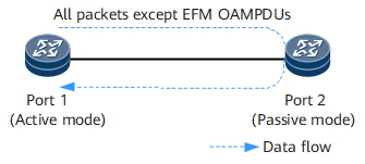
A device enabled with remote loopback discards all data frames except OAMPDUs, causing a service interruption. To prevent impact on services, use remote loopback to check link connectivity and quality before a new network is used or after a link fault is rectified.
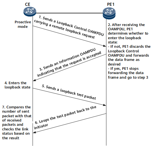
The local device calculates communication quality parameters such as the packet loss ratio on the current link based on the numbers of sent and received packets. Figure 4 shows the remote loopback process.
If the local device attempts to stop remote loopback, it sends a message to instruct the remote device to disable remote loopback. After receiving the message, the remote device disables remote loopback.
If remote loopback is left enabled, the remote device keeps looping back service data, causing a service interruption. To prevent this issue, a capability can be configured to disable remote loopback automatically after a specified timeout period. After the timeout period expires, the local device automatically sends a message to instruct the remote device to disable remote loopback.