PIM Control Messages
PIM routers exchange PIM control messages to implement multicast routing. A PIM control message is encapsulated in an IP packet, as shown in Figure 1.

In the header of an IP packet that contains a PIM control message:
The protocol type field is 103.
The destination address identifies a receiver. The destination address can be either a unicast address or a multicast address.
PIM Control Message Types
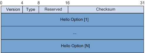
All PIM control messages use the same header format, as shown in Figure 2.


In PIM messages, unicast and multicast addresses are encapsulated in encoding formats, for example, group addresses in the Encoded-Group format, source addresses in the Encoded-Source format, and BSR addresses in the Encoded-Unicast format. The length of the address that can be encoded and encapsulated is variable, depending on the supported protocol type, such as IPv4 and IPv6.
Field |
Description |
|---|---|
Version |
PIM version. The value is 2. |
Type |
Message type:
|
Reserved |
Reserved |
Checksum |
Checksum |
Hello Messages
PIM devices periodically send Hello messages through all PIM interfaces to discover neighbors and maintain neighbor relationships.
In an IP packet that carries a Hello message, the source address is a local interface's address, the destination address is 224.0.0.13, and the TTL value is 1. The IP packet is transmitted in multicast mode.

Field |
Length |
Description |
|---|---|---|
Type |
4 bits |
Message type. |
Reserved |
4 bits |
Reserved. The field is set to 0 when the message is sent and is ignored when the message is received. |
Checksum |
8 bits |
Checksum. |
Option Type |
2 bytes |
Option type. For detailed values, see Table 3. |
Option Length |
2 bytes |
Length of the Option Value field. |
Option Value |
Variable length |
Parameter value. |
Option Type |
Option Value |
|---|---|
1 |
Holdtime: timeout period during which a neighbor remains in the reachable state |
2 |
The field consists of the following parts:
|
19 |
DR Priority: priority of a router interface, used to elect a designated router (DR) |
20 |
Generation ID: a random number, indicating neighbor status. If the neighbor status changes, the random number is updated. When the router detects that the Hello messages received from an upstream device contain different Generation IDs, the router considers the upstream neighbor Down or the status of the upstream neighbor has changed. |
21 |
State Refresh Capable: interval for refreshing neighbor status |
24 |
Address List: secondary address list of PIM interfaces |
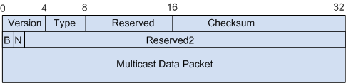
Register Messages
Register messages are used only in PIM-SM.
When a multicast source becomes active on a PIM-SM network, the source's DR sends a Register message to register with the rendezvous point (RP).
In an IP packet that carries a Register message, the source address is the address of the source's DR, and the destination address is the RP's address. The message is transmitted in unicast mode.
Field |
Length |
Description |
|---|---|---|
Type |
4 bits |
Message type. The value is 1. |
Reserved |
8 bits |
The field is set to 0 when the message is sent and is ignored when the message is received. |
Checksum |
16 bits |
Checksum. |
B |
1 bit |
Border bit. |
N |
1 bit |
Null-Register bit. |
Reserved2 |
30 bits. |
Reserved. The field is set to 0 when the message is sent and this field is ignored when the message is received. |
Multicast data packet |
Variable length |
The source's DR encapsulates the received multicast data in a Register message and sends the message to the RP. After decapsulating the message, the RP learns the (S, G) information of the multicast data packet. |
A multicast source can send data to multiple groups, and therefore a source's DR must send Register messages to the RP of each target multicast group. A Register message is encapsulated only in one multicast data packet, so the packet carries only one copy of (S, G) information.
In the register suppression period, a source's DR sends Null-Register messages to notify the RP of the source's active state. A Null-Register message contains only an IP header, including the source address and group address. After the register suppression times out, the source's DR encapsulates a multicast data packet in a Register message again.
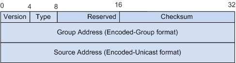
Register-Stop Messages
Register-Stop messages are used only in PIM-SM.
Receivers stop requesting a multicast group's data through the RP.
The RP stops serving a multicast group.
Multicast data has been switched from a rendezvous point tree (RPT) to a shortest path tree (SPT).
After receiving a Register-Stop message, a source's DR stops using the Register message to encapsulate multicast data packets and enters the register suppressed state.
In an IP packet that carries a Register-Stop message, the source address is the RP's address, and the destination address is the source DR's address. The message is transmitted in unicast mode.
Field |
Length |
Description |
|---|---|---|
Type |
4 bits |
Message type. The value is 2. |
Reserved |
8 bits |
Reserved. The field is set to 0 when the message is sent and this field is ignored when the message is received. |
Checksum |
16 bits |
Checksum. |
Group Address (Encoded-Group format) |
Variable length |
Multicast group address G. |
Source Address (Encoded-Unicast format) |
Variable length |
Multicast source address S. |
An RP can serve multiple groups, and a group can receive data from multiple sources. Therefore, an RP may simultaneously perform multiple (S, G) registrations.
A Register-Stop message carries only one piece of (S, G) information. When an RP sends a Register-Stop message to a source's DR, the RP can terminate only one (S, G) registration.
After receiving the Register-Stop message carrying the (S, G) information, the source's DR stops encapsulating (S, G) packets. The source still uses Register messages to encapsulate packets and send the packets to other groups.
Join/Prune Messages
A Join/Prune message can contain both Join messages and Prune messages. A Join/Prune message that contains only Join information is called a Join message. A Join/Prune message that contains only Prune information is called a Prune message.
When a PIM device no longer has multicast receivers, it sends Prune messages through its upstream interfaces to instruct the upstream device to stop forwarding packets to the network segment on which the PIM device resides.
When a receiver starts to require data from a PIM-SM network, the receiver's DR sends a Join message through the reverse path forwarding (RPF) interface towards the RP to instruct the upstream neighbor to forward packets to the receiver. The Join message is sent upstream hop by hop to set up an RPT.
When an RP triggers an RPT-to-SPT switchover, the RP sends a Join message through the RPF interface that points to the source to instruct the upstream neighbor to forward packets to the network segment. The Join message is sent upstream hop by hop to set up an SPT.
When a receiver's DR triggers an RPT-to-SPT switchover, the DR sends a Join message through the RPF interface that points to the source to instruct the upstream neighbor to forward packets to the network segment. The Join message is sent upstream hop by hop to set up an SPT.
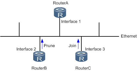
A PIM shared network segment may be connected to a downstream interface and multiple upstream interfaces. If an upstream interface sends a Prune message, but other upstream interfaces still require multicast packets, these interfaces that require multicast packets must send Join messages within the override-interval. Otherwise, the downstream interface responsible for forwarding packets on the network segment performs the prune action.
- If PIM is enabled on the interfaces of user-side routers, a receiver's DR is elected, and outbound interfaces are added to the PIM DR's outbound interface list. The PIM DR then sends Join messages to the RP.
As shown in Figure 7, interface 1 on DeviceA is a downstream interface, and interface 2 on DeviceB and interface 3 on DeviceC are upstream interfaces. If DeviceB sends a Prune message through interface 2, interface 3 of DeviceC and interface 1 of DeviceA will receive this message. If DeviceC still wants to receive the multicast data of the group, DeviceC must send a Join message within the override-interval. This message will notify interface 1 of DeviceA that a downstream router still wants to receive the multicast data. Therefore, DeviceA does not perform the prune action.
In an IP packet that carries a Join/Prune message, the source address is a local interface's address, the destination address is 224.0.0.13, and the TTL value is 1. The message is transmitted in multicast mode.
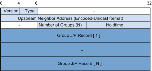
Field |
Length |
Description |
|---|---|---|
Type |
4 bits |
Message type. The value is 3. |
Upstream Neighbor Address (Encoded-Unicast format) |
Variable length |
Upstream neighbor's address, that is, the address of the router's downstream interface that receives the Join/Prune message and performs the Join or Prune action. |
Number of Groups |
8 bits |
Number of groups contained in the message. |
Holdtime |
16 bits |
Duration (in seconds) that the router lets an interface remain in the Join or Prune state after receiving a Join/Prune message. |
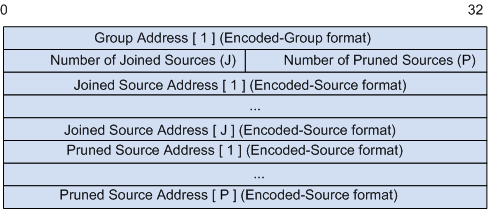
Group Address (Encoded-Group format) |
Variable length |
Group address. |
Number of Joined Sources |
16 bits |
Number of sources whose multicast traffic is requested. |
Number of Pruned Sources |
16 bits |
Number of sources whose multicast traffic is no longer requested. |
Joined Source Address (Encoded-Source format) |
Variable length |
Address of the source whose multicast traffic is requested. |
Pruned Source Address (Encoded-Source format) |
Variable length |
Address of the source whose multicast traffic is no longer requested. |
Bootstrap Messages
Bootstrap messages are used only in PIM-SM.
When a dynamic RP is used on a PIM-SM network, candidate-bootstrap routers (C-BSRs) periodically send Bootstrap messages through all PIM interfaces to participate in BSR election. The winner continues to send Bootstrap messages carrying RP-Set information to all PIM devices in the domain.
In an IP packet that carries a Bootstrap message, the source address is a PIM interface's address, the destination address is 224.0.0.13, and the TTL value is 1. The packet is transmitted in multicast mode and is forwarded hop by hop on the PIM-SM network and is flooded on the entire network.
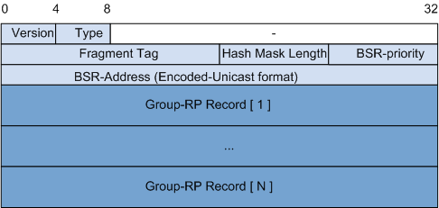
Field |
Length |
Description |
|---|---|---|
Type |
4 bits |
Message type. The value is 4. |
Fragment Tag |
16 bits |
Random number used to distinguish the Bootstrap message. |
Hash Mask length |
8 bits |
Length of the hash mask of the C-BSR. |
BSR-priority |
8 bits |
C-BSR priority. |
BSR-Address (Encoded-Unicast format) |
Variable length |
C-BSR address. |
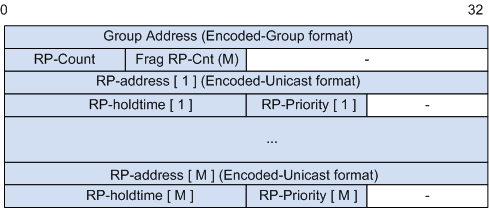
Group Address (Encoded-Group format) |
Variable length |
Group address. |
RP-Count |
8 bits |
Total number of C-RPs that want to serve the group. |
Frag RP-Cnt |
8 bits |
Number of C-RP addresses included in this fragment of the Bootstrap message for the corresponding group range. This field facilitates parsing of the RP-Set for a given group range, when carried over more than one fragment. |
RP-address (Encoded-Unicast format) |
Variable length |
C-RP address. |
RP-holdtime |
16 bits |
Aging time of the advertisement message sent by the C-RP. |
RP-Priority |
8 bits |
C-RP priority. |
The BSR boundary can be set using the pim bsr-boundary command on a PIM interface. Multiple BSR boundary interfaces divide the network into different PIM-SM domains. Bootstrap messages cannot pass through the BSR boundary.
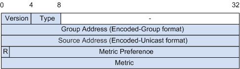
Assert Messages
On a shared network segment, if a PIM device receives an (S, G) packet from the downstream interface of the (S, G) or (*, G) entry, other forwarders exist on the network segment. The router then sends an Assert message through the downstream interface to participate in the forwarder election. The devices that fail in the forwarder election stop forwarding multicast packets through the downstream interface.
In an IP packet that carries an Assert message, the source address is a local interface's address, the destination address is 224.0.0.13, and the TTL value is 1. The packet is transmitted in multicast mode.
Field |
Length |
Description |
|---|---|---|
Type |
4 bits |
Message type. The value is 5. |
Group Address (Encoded-Group format) |
Variable length |
Group address. |
Source address (Encoded-Unicast format) |
Variable length |
This field is a multicast source address if a unique forwarder is elected for (S, G) entries, and this field is 0 if a unique forwarder is elected for (*, G) entries. |
R |
1 bit |
RPT bit. This field is 0 if a unique forwarder is elected for (S, G) entries, and this field is 1 if a unique forwarder is elected for (*, G) entries. |
Metric Preference |
31 bits |
Preference of the unicast path to the source address. If the R field is 1, this field indicates the preference of the unicast path to the RP. |
Metric |
32 bits |
Cost of the unicast route to the source address. If the R field is 1, this field indicates the cost of the unicast path to the RP. |
Graft Messages
The Graft message is applicable only to PIM-DM.
On the PIM-DM network, when a router receives a Report message from a host, the router sends a Graft message through the upstream interface of the related (S, G) entry if the router is not on the SPT. The upstream neighbor immediately restores the forwarding of the downstream interface. If the upstream neighbor is not on the SPT, the neighbor forwards the Graft message upstream.
The source address of the IP packet that carries the Graft message is the local interface address and the destination address is the RPF neighbor. The packet is sent in unicast mode.
The format of the Graft message is the same as that of the Join/Prune message except for the values of some fields. Table 9 shows the values of these fields in the Graft message.
Field |
Description |
|---|---|
Type |
Message type. The value is 6. |
Joined source address (Encoded-Source format) |
Source address of the (S, G) to be grafted. |
Number of Pruned Sources |
This field is not used in a Graft message. The value is 0. |
HoldTime |
This field is not used in a Graft message. The value is 0. |
Graft-Ack Messages
The Graft-Ack message is applicable only to PIM-DM.
On the PIM-DM network, when a router receives a Graft message from a downstream device, the router restores the forwarding of the related downstream interface and sends a Graft-Ack message through the downstream interface to acknowledge the Graft message. If the router that sent the Graft message does not receive any Graft-Ack message in the set time, the router considers that the upstream device does not receive the Graft message and resends it.
The source address of the IP packet that carries the Graft-Ack message is the downstream interface address of an upstream device and the destination address is the address of the router that sent the Graft message. The packet is sent in unicast mode.
The format of the Graft-Ack message is the same as that of the Graft message, and the Graft-Ack message copies the contents of the Graft message. The values of some fields in the Graft-Ack message are different from those in the Graft message, as described in Table 10.
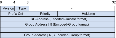
C-RP Advertisement Messages
C-RP Advertisement messages are used only in PIM-SM.
When a dynamic RP is used, C-RPs periodically send Advertisement messages to notify the BSR of the range of groups they want to serve.
In an IP packet that carries an Advertisement message, the source address is the source's C-RP address, and the destination address is the BSR's address. The packet is transmitted in unicast mode.
Field |
Length |
Description |
|---|---|---|
Type |
4 bits |
Message type. The value is 8. |
Prefix-Cnt |
8 bits |
Prefix value of the multicast address |
Priority |
8 bits |
C-RP priority |
Holdtime |
16 bits |
Aging time of the Advertisement message |
RP-Address (Encoded-Unicast format) |
Variable length |
C-RP address |
Group Address (Encoded-Group format) |
Variable length |
Group address |
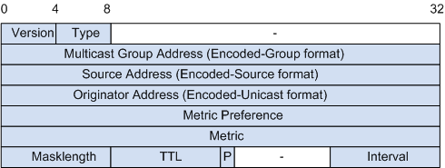
State-Refresh Message
The State-Refresh message is applicable only to PIM-DM.
In the PIM-DM network, to avoid that the interface restores forwarding because the prune timer times out, the first-hop router nearest to the source periodically triggers State-Refresh messages. The State-Refresh message is flooded in the entire network and the statuses of prune timers on all routers are refreshed.
The source address of the IP packet encapsulated with the State-Refresh message is the downstream interface address, the destination address is 224.0.0.13, and the TTL value is 1. The packet is sent in multicast mode.
Field |
Length |
Description |
|---|---|---|
Type |
4 bits |
Indicates the message type. The value is 9. |
Multicast Group Address (Encoded-Groupformat) |
Variable length |
Indicates the group address. |
Source Address (Encode-Source format) |
Variable length |
Indicates the source address. |
Originator Address (Encoded-Unicast format) |
Variable length |
Indicates the address of the first-hop router. |
Metric Preference |
32 bits |
Indicates the priority of the unicast route to the source. |
Metric |
32 bits |
Indicates the cost of the unicast route to the source. |
Masklength |
8 bits |
Indicates the address mask length of the unicast route to the source. |
TTL |
8 bits |
Indicates the TTL of the State-Refresh message. The TTL is used to limit the transmission range of the messages. The TTL value is reduced by 1 each time the State-Refresh message is forwarded by a router. |
P |
1 bit |
Indicates the prune indicator flag. If the State-Refresh message is sent out through the pruned interface, P is 1. Otherwise, P is 0. |
Interval |
8 bits |
Indicates the interval for sending State-Refresh messages. |