Replacing an Optical Module
Context

Laser beams will cause eye damage. Do not look into bores of Optical Modules or optical fibers without eye protection.

- Huawei-certified Optical Modules are strongly recommended because non-Huawei-certified Optical Modules cannot ensure transmission reliability and may affect service stability.
- Optical Modules are hot swappable, and you do not need to power off the device when replacing Optical Modules.
- Optical Modules are electrostatic-sensitive components. Therefore, you must take ESD protection measures when replacing Optical Modules.
Only external Optical Modules can be replaced and pluggable. Built-in Optical Modules cannot be replaced.
Follow these guidelines when replacing an Optical Module:
- Replacing an Optical Module interrupts service transmission. Therefore, replace an Optical Module only when you confirm that the Optical Module has failed.
- Ensure that the new Optical Module has the same center wavelength and complies with the same standards as the old one.
- When replacing an Optical Module, ensure that no optical fiber is connected to the Optical Module. Install or remove optical fibers carefully to avoid damages to fiber connectors. Exercise caution when installing or removing optical fibers to prevent damage to the Optical Module.
- After removing the optical fibers from an Optical Module, cover the fiber connectors with dust caps. Place the optical fibers in an appropriate place to prevent them from swinging.
- Use assistant tools like the tweezers delivered with the device to remove an Optical Module in a confined space.
- After removing a copper transceiver, wait at least 2 seconds before inserting a new one. Otherwise, the port may fail to go Up. If the port cannot go Up, remove the copper transceiver and install it 2 seconds later.
- If the LINK indicator on an optical port with two optical fibers is off, swap the two optical fibers.
- During the replacement, keep the bores of the Optical Module and fiber connectors clean, protecting them from dust and other contamination sources. Install dust plugs on idle optical ports.
Tools and Accessories
ESD wrist strap or ESD gloves
Spare Optical Module
Dust caps
(Optional) Optical port dust plug
(Optional) Tweezers
Procedure
Check the location of the Optical Module to be replaced.
Before pulling out an Optical Module that is to be replaced, you should first check the location of the module, for example, the cabinet and chassis where the Optical Module resides. Then, locate the Optical Module to be replaced in the chassis and attach a label to the panel to identify the Optical Module.
Run the display interface interface-type interface-number command to view and record the type of the Optical Module to be replaced, as the following output in bold displays:
<HUAWEI> display interface Gigabitethernet0/1/0
GigabitEthernet0/1/0 current state : DOWN
Line protocol current state : DOWN
Description: HUAWEI, GigabitEthernet0/1/0 Interface (ifindex: 7)
Route Port,The Maximum Transmit Unit is 1500
IP Sending Frames' Format is PKTFMT_ETHNT_2, Hardware address is 001a-2b11-4d51
The Vendor PN is RTXM191-400
The Vendor Name is WTD
Port BW: 1G, Transceiver max BW: 1G, Transceiver Mode: SingleMode
WaveLength: 1310nm, Transmission Distance: 10km
Rx Power:  -1.43dBm, normal range: [-19.014,  -3.000]dBm
Tx Power:  -4.86dBm, normal range: [-6.859,  -2.857]dBm
Loopback:none, full-duplex mode, negotiation: disable, Pause Flowcontrol:Receive Enable and Send Enable
Last physical up time   : 2012-10-11 10:01:20
Last physical down time : 2012-10-11 10:01:19
Current system time: 2012-10-12 09:53:44
Statistics last cleared:2012-10-12 09:02:03
    Last 300 seconds input rate: 0 bits/sec, 0 packets/sec
    Last 300 seconds output rate: 0 bits/sec, 0 packets/sec
    Input peak rate 88 bits/sec, Record time: 2012-10-12 09:03:45
    Output peak rate 78 bits/sec, Record time: 2012-10-12 09:02:54
    Input: 2144 bytes, 22 packets
    Output: 614 bytes, 7 packets
    Input:
      Unicast: 21 packets, Multicast: 1 packets
      Broadcast: 0 packets, JumboOctets: 0 packets
      CRC: 0 packets, Symbol: 0 packets
      Overrun: 0 packets, InRangeLength: 0 packets
      LongPacket: 0 packets, Jabber: 0 packets, Alignment: 0 packets
      Fragment: 0 packets, Undersized Frame: 0 packets
      RxPause: 0 packets
    Output:
      Unicast: 6 packets, Multicast: 1 packets
      Broadcast: 0 packets, JumboOctets: 0 packets
      Lost: 0 packets, Overflow: 0 packets, Underrun: 0 packets
      System: 0 packets, Overruns: 0 packets
      TxPause: 0 packets
    Last 300 seconds input utility rate:  0.00%
    Last 300 seconds output utility rate: 0.00%
Record the location of the cables and check whether the labels on the cables are correct and clear. If the labels are hard to identify, re-make labels and re-label the cables in case the cables are not connected properly.
Wear the ESD gloves or wrist strap and connect the grounding terminal to the ESD jack on the rack.
- Pull out the Optical Module to be replaced.
- Remove the optical cables from the connector and cover the connector with a dust cap.
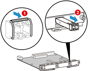
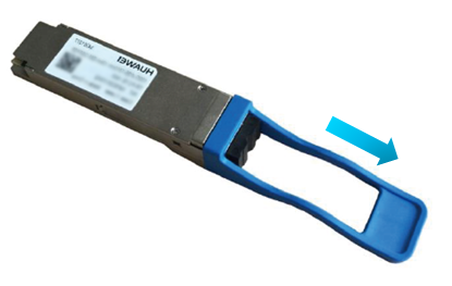
- Pull the bail-clasp or pull-tab latch on the optical module, as shown in Figure2 and Figure3 respectively.

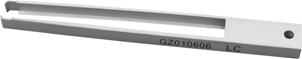
When the operation space is insufficient, you can use a fiber interface clamp to remove an Optical Module. Figure1 shows the appearance of a fiber interface clamp.
- Hold the handle to pull out the Optical Module carefully from the optical interface, as (2) shown in Figure2. When installing a CFP Optical Module, hold the screw rods with both hands, and slightly pull out the Optical Module from the optical port.
The QSFP28 and QSFP-DD modules will get very hot during operation. To prevent injuries, do not touch the module shells when removing the modules.
- Place the removed Optical Module in the ESD bag.
- Insert the new Optical Module into the optical interface.
- Take out the new Optical Module from the ESD bag and check whether there is any damage or component missing. Check whether the new Optical Module is of the same type as the Optical Module to be replaced.
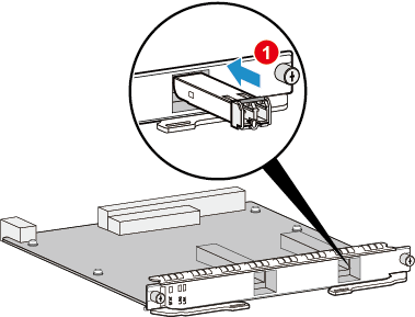
- Insert the new Optical Module into the optical interface, as shown in Figure 4. When the click of the reed in the Optical Module is heard, it indicates that the Optical Module is correctly inserted. If the new Optical Module is a CFP one, insert the new Optical Module into the optical port of the card, push the transceiver panel horizontally into the connector using even force with both thumbs. After the transceiver is inserted, push the transceiver slightly to ensure that it has reached the stop position. Pull out the two screw rods slightly to ensure that they can properly function. Pre-tighten one of the screw rods. Then, tighten the other screw rod. After that, tighten the first screw rod. To prevent the Optical Module from getting loosened due to vibration or collision, you are advised to use a screwdriver to tighten the screw rods.
Do not insert an Optical Module reversely. If an Optical Module cannot be completely inserted into an optical port, do not force it into the port. Instead, turn the Optical Module over and try again.
- Remove the dust cap from the connector and insert the optical cables in the original sequence.
- Verify the functions of the new Optical Module.
Then, you can verify the functions of the new Optical Module in the following ways:
- Check whether the LINK indicator on the optical interface works normally. If the indicator is green, it indicates that the links connected to the interface are Up.
- Run the display interface interface-type interface-number command on the console interface to view the type and running status of the new Optical Module. Check whether the type of the new Optical Module corresponds to that of the original Optical Module, as the following output in bold displays:
<HUAWEI> display interface Gigabitethernet0/1/0
GigabitEthernet0/1/0 current state : DOWN
Line protocol current state : DOWN
Description: HUAWEI, GigabitEthernet0/1/0 Interface (ifindex: 7)
Route Port,The Maximum Transmit Unit is 1500
IP Sending Frames' Format is PKTFMT_ETHNT_2, Hardware address is 001a-2b11-4d51
The Vendor PN is RTXM191-400
The Vendor Name is WTD
Port BW: 1G, Transceiver max BW: 1G, Transceiver Mode: SingleMode
WaveLength: 1310nm, Transmission Distance: 10km
Rx Power:  -1.43dBm, normal range: [-19.014,  -3.000]dBm
Tx Power:  -4.86dBm, normal range: [-6.859,  -2.857]dBm
Loopback:none, full-duplex mode, negotiation: disable, Pause Flowcontrol:Receive Enable and Send Enable
Last physical up time   : 2012-10-11 10:01:20
Last physical down time : 2012-10-11 10:01:19
Current system time: 2012-10-12 09:53:44
Statistics last cleared:2012-10-12 09:02:03
    Last 300 seconds input rate: 0 bits/sec, 0 packets/sec
    Last 300 seconds output rate: 0 bits/sec, 0 packets/sec
    Input peak rate 88 bits/sec, Record time: 2012-10-12 09:03:45
    Output peak rate 78 bits/sec, Record time: 2012-10-12 09:02:54
    Input: 2144 bytes, 22 packets
    Output: 614 bytes, 7 packets
    Input:
      Unicast: 21 packets, Multicast: 1 packets
      Broadcast: 0 packets, JumboOctets: 0 packets
      CRC: 0 packets, Symbol: 0 packets
      Overrun: 0 packets, InRangeLength: 0 packets
      LongPacket: 0 packets, Jabber: 0 packets, Alignment: 0 packets
      Fragment: 0 packets, Undersized Frame: 0 packets
      RxPause: 0 packets
    Output:
      Unicast: 6 packets, Multicast: 1 packets
      Broadcast: 0 packets, JumboOctets: 0 packets
      Lost: 0 packets, Overflow: 0 packets, Underrun: 0 packets
      System: 0 packets, Overruns: 0 packets
      TxPause: 0 packets
    Last 300 seconds input utility rate:  0.00%
    Last 300 seconds output utility rate: 0.00%
- Check whether there is any new alarm or performance event.
- Check whether the services are normal on the new Optical Module. If the services are normal, it indicates that replacing an Optical Module is successful.
If the new Optical Module fails to return to the normal state, you should contact a Huawei local office for timely technical support.
Follow-up Procedure
After replacing an Optical Module, collect the tools. If an Optical Module that is replaced and is confirmed to be faulty, you should fill in the Offsite Repair Card for Faulty Materials, and send the card and the faulty Optical Module to a Huawei local office for timely maintenance.