< Home

S5720-32X-EI-24S-DC

Version Mapping

Table 1 lists the mapping between the S5720-32X-EI-24S-DC chassis and software versions.

Table 1 Version mapping

Series

Model

Software Version
S5720-EI S5720-X-EI S5720-32X-EI-24S-DC

V200R009C00 and later versions

Appearance and Structure
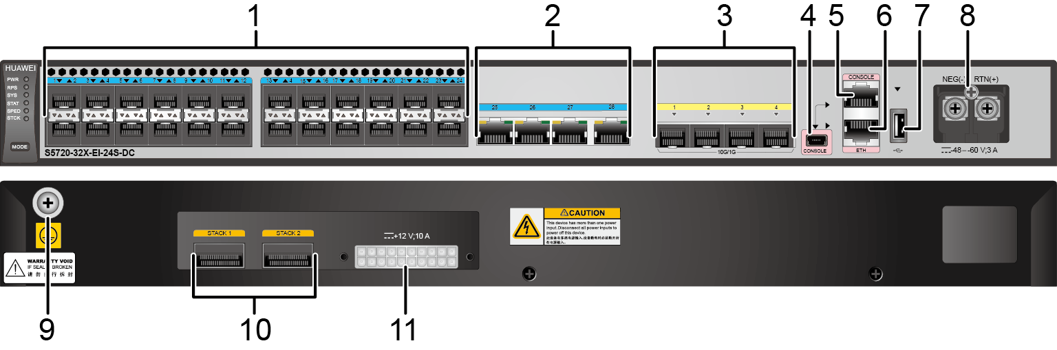
Figure 1 S5720-32X-EI-24S-DC appearance
1 Twenty-four 100/1000BASE-X ports 2 Four 10/100/1000BASE-T ports
3 Four 10GE SFP+ ports 4 One mini USB port
5 One console port
NOTE:

It is used with a console cable. The console cable is not delivered with the switch and needs to be separately purchased if needed.

6 One ETH management port
7 One USB port 8 DC power terminal
NOTE:

It is used together with a DC Power Cable.

9 Ground screw
NOTE:
It is used with a ground cable.
10 Two QSFP+ stack optical ports
Applicable modules and cables:
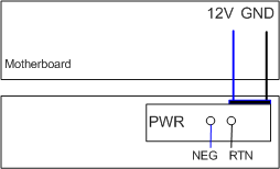
11 RPS socket
NOTE:

It is used with an RPS cable, which is not hot swappable.

- -

Port Description

10/100/1000BASE-T port
A 10/100/1000BASE-T Ethernet electrical port sends and receives service data at 10/100/1000 Mbit/s, and must use an Ethernet cable. Table 2 describes the attributes of a 10/100/1000BASE-T Ethernet electrical port.
Table 2 Attributes of a 10/100/1000BASE-T Ethernet electrical port

Attribute

Description

Connector type

RJ45

Standards compliance

IEEE802.3, IEEE802.3u, IEEE802.3ab

Working mode

10/100/1000 Mbit/s auto-sensing

Maximum transmission distance

100 m

100/1000BASE-X port
A 100/1000BASE-X port can send and receive data at 100 Mbit/s or 1000 Mbit/s. Table 3 describes the attributes of a 100/1000BASE-X port.
Table 3 Attributes of a 100/1000BASE-X port

Attribute

Description

Connector type

LC/PC

Optical interface attributes

Depend on the optical module used

Standards compliance

IEEE802.3z

Working mode

100/1000 Mbit/s auto-sensing

10GE SFP+ port
A 10GE SFP+ Ethernet optical port supports auto-sensing to 1000 Mbit/s. It sends and receives service data at 1000 Mbit/s or 10 Gbit/s. Table 4 describes the attributes of a 10GE SFP+ Ethernet optical port.
Table 4 Attributes of a 10GE SFP+ port

Attribute

Description

Connector type

LC/PC

Optical port attributes

Depend on the optical module used

Standards compliance

IEEE802.3ae

Working mode

GE/10GE auto-sensing

QSFP+ stack optical port
QSFP+ stack optical ports can only be used for stack connection. Table 5 describes the attributes of a QSFP+ stack optical port.
Table 5 Attributes of a QSFP+ stack optical port

Attribute

Description

Connector type

MPO

Optical port attributes

Depend on the optical module used

Standards compliance

IEEE802.3ae

Console port
The console port is connected to a console for on-site configuration. The port must use a console cable. The console port is used when a switch is powered on for the first time. For details about the attributes of a console port, see Table 6.
Table 6 Attributes of a console port

Attribute

Description

Connector type

RJ45

Standards compliance

RS-232

Working mode

Duplex Universal Asynchronous Receiver/Transmitter (UART)

Baud rate

9600 bit/s, 19200 bit/s, 38400 bit/s, 57600 bit/s, or 115200 bit/s

Default value: 9600 bit/s

Mini USB port

The mini USB port is connected to a console for on-site configuration. When both the Mini USB and console port have a cable connected, only the Mini USB port works.

ETH management port
You can connect a switch to a configuration terminal or network management workstation through the ETH management port to configure the switch locally or remotely. The port must use an Ethernet cable. You can choose to download the software package through the ETH management port in the BootLoad menu. File transfer through the ETH management port is faster than transfer through the console port. Table 7 describes the attributes of an ETH management port.
Table 7 Attributes of an ETH management port

Attribute

Description

Connector type

RJ45

Standards compliance

IEEE802.3

Working mode

10/100 Mbit/s auto-sensing

Maximum transmission distance

100 m

In V200R012C00 and later versions, you can log in to the switch that contains the ETH management port for the first time through the ETH port. For details, see "First Login to a Switch" in the Configuration Guide - Basic Configuration. If you have logged in to the device for the first time by pressing and holding the MODE button for 6 seconds or longer and saved the configuration, the default configuration on the ETH port will be cleared. In this case, you cannot log in to the switch for the first time through the ETH port. You are advised to log in to the switch for the first time through the ETH port.
USB port
The USB port can have a USB flash drive connected to upgrade the switch, or transfer configuration files or other files. The USB port of the S5720-EI does not support USB 1.1 and can only connect to a USB flash drive that complies with USB 2.0.
USB flash drives from different vendors differ in model compatibility and drivers. If a USB flash drive cannot be used, try to replace it with another one from a mainstream vendor. Switches support a maximum of 128 GB USB flash drives.

Indicator Description

The S5720-32X-EI-24S-DC has 24 downlink optical port indicators, whereas the S5720-32X-EI-AC has 24 downlink electrical port indicators. Symbols and meanings of other indicators on the two switch models are the same. For details, see Indicator Description.

Power Supply Configuration

The S5720-32X-EI-24S-DC has a built-in power module and does not support pluggable power modules. It can connect to an RPS1800 power supply for power redundancy.

Figure 2 shows the power supply mode of a single DC power module. The built-in DC power module (PWR) receives DC power from an external power source and provides a 12 V output to the chassis.
Figure 2 Power supply by a single DC power module

NEG: negative wire

RTN: positive wire

GND: 12 V reference ground

Heat Dissipation

The S5720-32X-EI-24S-DC has a built-in fan for forced air cooling. Air flows in from the left side and front panel, and exhausts from the right side.

This figure only shows the airflow direction and does not depict the actual device.

Technical Specifications

Table 8 lists technical specifications of the S5720-32X-EI-24S-DC.

Table 8 Technical specifications

Item

Description

Memory (RAM)

2 GB

Flash

512 MB in total. To view the available flash memory size, run the display version command.

Mean time between failures (MTBF)

82.54 years

Mean time to repair (MTTR)

2 hours

Availability

> 0.99999

Service port surge protection

Common mode: ±6 kV

Power supply surge protection

±1 kV in differential mode, ±2 kV in common mode

Dimensions (H x W x D)

43.6 mm x 442.0 mm x 220.0 mm (1.72 in. x 17.4 in. x 8.7 in.)

Weight (with packaging)

4.2 kg (9.26 lb)

Stack ports

  • Two fixed QSFP+ stack ports on the rear card

RTC

Supported

RPS

Supported

PoE

Not supported

Rated voltage range

-48 V DC to -60 V DC

Maximum voltage range

-36 V DC to -72 V DC

Maximum power consumption (100% throughput, full speed of fans)

58.9 W

Typical power consumption (30% of traffic load)
  • Tested according to ATIS standard
  • EEE enabled
  • No PoE power consumption

55.46 W

Operating temperature

0°C to 45°C (32°F to 113°F) at an altitude of 0-1800 m (0-5906 ft.)
NOTE:

When the altitude is 1800-5000 m (5906-16404 ft.), the highest operating temperature reduces by 1°C (1.8°F) every time the altitude increases by 220 m (722 ft.).

Storage temperature

-40°C to +70°C (-40°F to +158°F)

Noise under normal temperature (27°C, sound power)

< 49.3 dB(A)

Relative humidity

5% to 95%, noncondensing

Operating altitude

0-2000 m (0-6562 ft.)

Certification

  • EMC certification
  • Safety certification
  • Manufacturing certification

Part number

02350NHE
Copyright © Huawei Technologies Co., Ltd.
< Previous topic Next topic >