< Home

S5720-56C-EI-48S-AC

Version Mapping

Table 1 lists the mapping between the S5720-56C-EI-48S-AC chassis and software versions.

Table 1 Version mapping

Series

Model

Software Version
S5720-EI S5720-C-EI S5720-56C-EI-48S-AC

V200R007C00 and later versions

NOTE:
This model does not match V200R007C10.

Appearance and Structure
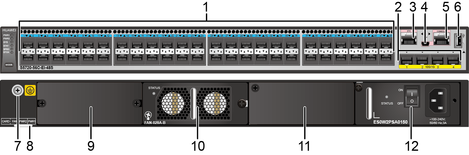
Figure 1 S5720-56C-EI-48S-AC appearance
1 Forty-eight 100/1000BASE-X ports 2 Four 10GE SFP+ ports
3 One ETH management port 4 One mini USB port
5 One console port
NOTE:

It is used with a console cable. The console cable is not delivered with the switch and needs to be separately purchased if needed.

6 One USB port
7 Ground screw
NOTE:
It is used with a ground cable.
8 ESN label
NOTE:

You can draw it out to view the ESN and MAC address of the switch.

9 Rear card slot 10 Fan slot
NOTE:

Applicable fan module: FAN-028A-B Fan Module

11 Power module slot 2
NOTE:
12 Power module slot 1
NOTE:

Port Description

100/1000BASE-X port
A 100/1000BASE-X port can send and receive data at 100 Mbit/s or 1000 Mbit/s. Table 2 describes the attributes of a 100/1000BASE-X port.
Table 2 Attributes of a 100/1000BASE-X port

Attribute

Description

Connector type

LC/PC

Optical interface attributes

Depend on the optical module used

Standards compliance

IEEE802.3z

Working mode

100/1000 Mbit/s auto-sensing

10GE SFP+ port
A 10GE SFP+ Ethernet optical port supports auto-sensing to 1000 Mbit/s. It sends and receives service data at 1000 Mbit/s or 10 Gbit/s. Table 3 describes the attributes of a 10GE SFP+ Ethernet optical port.
Table 3 Attributes of a 10GE SFP+ port

Attribute

Description

Connector type

LC/PC

Optical port attributes

Depend on the optical module used

Standards compliance

IEEE802.3ae

Working mode

GE/10GE auto-sensing

Console port
The console port is connected to a console for on-site configuration. The port must use a console cable. The console port is used when a switch is powered on for the first time. For details about the attributes of a console port, see Table 4.
Table 4 Attributes of a console port

Attribute

Description

Connector type

RJ45

Standards compliance

RS-232

Working mode

Duplex Universal Asynchronous Receiver/Transmitter (UART)

Baud rate

9600 bit/s, 19200 bit/s, 38400 bit/s, 57600 bit/s, or 115200 bit/s

Default value: 9600 bit/s

Mini USB port

The mini USB port is connected to a console for on-site configuration. When both the Mini USB and console port have a cable connected, only the Mini USB port works.

ETH management port
You can connect a switch to a configuration terminal or network management workstation through the ETH management port to configure the switch locally or remotely. The port must use an Ethernet cable. You can choose to download the software package through the ETH management port in the BootLoad menu. File transfer through the ETH management port is faster than transfer through the console port. Table 5 describes the attributes of an ETH management port.
Table 5 Attributes of an ETH management port

Attribute

Description

Connector type

RJ45

Standards compliance

IEEE802.3

Working mode

10/100 Mbit/s auto-sensing

Maximum transmission distance

100 m

In V200R012C00 and later versions, you can log in to the switch that contains the ETH management port for the first time through the ETH port. For details, see "First Login to a Switch" in the Configuration Guide - Basic Configuration. If you have logged in to the device for the first time by pressing and holding the MODE button for 6 seconds or longer and saved the configuration, the default configuration on the ETH port will be cleared. In this case, you cannot log in to the switch for the first time through the ETH port. You are advised to log in to the switch for the first time through the ETH port.
USB port
The USB port can have a USB flash drive connected to upgrade the switch, or transfer configuration files or other files. The USB port of the S5720-EI does not support USB 1.1 and can only connect to a USB flash drive that complies with USB 2.0.
USB flash drives from different vendors differ in model compatibility and drivers. If a USB flash drive cannot be used, try to replace it with another one from a mainstream vendor. Switches support a maximum of 128 GB USB flash drives.

Indicator Description

The S5720-56C-EI-48S-AC has the same types of indicators as the S5720-36C-EI-28S-AC. For details, see Indicator Description.

Power Supply Configuration

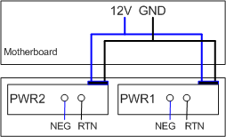
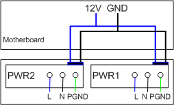
The S5720-56C-EI-48S-AC uses pluggable power modules. It can be configured with a single power module or double power modules for 1+1 power redundancy. Pluggable AC and DC power modules can be used together in the same switch.

Figure 2 shows the power supply connections of dual DC power modules. After DC power is transmitted to the PWR module, the PWR module provides 12 V output voltage, and the motherboard provides power for the entire device.
Figure 2 Power supply connections of dual DC power modules

NEG: negative wire

RTN: positive wire

GND: 12 V reference ground

Figure 3 shows the power supply connections of dual AC power modules. After AC power is transmitted to the PWR module, the PWR module provides 12 V output voltage, and the motherboard provides power for the entire device.
Figure 3 Power supply connections of dual AC power modules

L: Live wire

N: Neutral wire

PGND: Protection ground wire

GND: 12 V reference ground

Heat Dissipation

The S5720-56C-EI-48S-AC uses pluggable fan modules for forced air cooling. Air flows in from the left side, right side, and front panel, and exhausts from the rear panel.

This figure only shows the airflow direction and does not depict the actual device.

Technical Specifications

Table 6 lists technical specifications of the S5720-56C-EI-48S-AC.

Table 6 Technical specifications

Item

Description

Memory (RAM)

2 GB

Flash

512 MB in total. To view the available flash memory size, run the display version command.

Mean time between failures (MTBF)

73.91 years when no card is configured; 68.42 years when a 2-port 10GE SFP+ interface card is configured; 66.63 years when a 2-port 10GE RJ45 interface card is configured; 66.77 years when a stack card is configured

Mean time to repair (MTTR)

2 hours

Availability

> 0.99999

Service port surge protection

Ports on the 2-port 10GE RJ45 rear interface card: ±2 kV in common mode

Power supply surge protection

  • Using AC power modules: ±6 kV in differential mode, ±6 kV in common mode
  • Using DC power modules: ±1 kV in differential mode, ±2 kV in common mode

Dimensions (H x W x D)

44.4 mm x 442.0 mm x 420.0 mm (1.75 in. x 17.4 in. x 16.5 in.)

Weight (with packaging)

10.1 kg (22.27 lb)

Stack ports

  • Ports on the 2-port 10GE SFP+ rear interface card
  • Ports on the 2-port 10GE RJ45 rear interface card
  • Ports on the 2-port QSFP+ rear stack card

RTC

Supported

RPS

Not supported

PoE

Not supported

Rated voltage range

100 V AC to 240 V AC, 50/60 Hz

-48 V DC to -60 V DC

Maximum voltage range

90 V AC to 264 V AC, 47 Hz to 63 Hz

-36 V DC to -72 V DC

Maximum power consumption (100% throughput, full speed of fans)

104 W

Typical power consumption (30% of traffic load)
  • Tested according to ATIS standard
  • EEE enabled
  • No PoE power consumption
  • 68.82 W (without card)
  • 76.55 W (with 2*10GE optical card)
  • 81.23 W (with 2*QSFP+ stack card)
  • 83.78 W (with 2*10GE electrical card)

Operating temperature

0°C to 45°C (32°F to 113°F) at an altitude of 0-1800 m (0-5906 ft.)

NOTE:

When the altitude is 1800-5000 m (5906-16404 ft.), the highest operating temperature reduces by 1°C (1.8°F) every time the altitude increases by 220 m (722 ft.).

Short-term operating temperature

-5°C to +50°C (23°F to 122°F) at an altitude of 0-1800 m (0-5906 ft.)

NOTE:

When the altitude is 1800-5000 m (5906-16404 ft.), the highest operating temperature reduces by 1°C (1.8°F) every time the altitude increases by 220 m (722 ft.).

The equipment can operate beyond the normal operating temperature range for a short-term period, but the following conditions must be met:
  • The equipment operates at a temperature of over 45°C (113°F) consecutively for at most 96 hours in one year.
  • The equipment operates at a temperature of over 45°C (113°F) for a total of no more than 360 hours in one year.
  • The equipment operates at a temperature of over 45°C (113°F) for no more in 15 times in one year.
The equipment may be damaged or experience unexpected exceptions if any of the preceding limits is exceeded.

The equipment cannot start when the temperature is lower than 0°C (32°F). The maximum distance of optical modules used in these conditions cannot exceed 10 km.

Storage temperature

-40°C to +70°C (-40°F to +158°F)

Noise under normal temperature (27°C, sound power)

< 51.2 dB(A)

Relative humidity

5% to 95%, noncondensing

Operating altitude

  • AC power modules configured: 0-5000 m (0-16404 ft.)
  • DC power modules configured: 0-2000 m (0-6562 ft.)

Certification

  • EMC certification
  • Safety certification
  • Manufacturing certification

Part number

02359558
Copyright © Huawei Technologies Co., Ltd.
< Previous topic Next topic >