S5720I-28X-PWH-SI-AC
Version Mapping
Table 1 lists the mapping between the S5720I-28X-PWH-SI-AC chassis and software versions.
Appearance and Structure
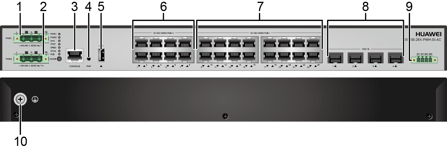
1 |
AC power input port 1 NOTE:
It must be used with the Phoenix connector, which is included in the installation accessory package. |
2 |
AC power input port 2 NOTE:
It must be used with the Phoenix connector, which is included in the installation accessory package. |
3 |
One console port |
4 |
One PNP button NOTICE:
To restore the factory settings and reset the switch, hold down the button for at least 6 seconds. To reset the switch, press the button. Resetting the switch will cause service interruption. Exercise caution when you press the PNP button. |
5 |
One USB port |
6 |
Eight PoE++ 10/100/1000BASE-T ports |
7 |
Sixteen PoE+ 10/100/1000BASE-T ports |
8 |
Four 10GE SFP+ ports |
9 |
Monitoring port NOTE:
It must be used with the Phoenix connector, which is included in the installation accessory package. The monitoring port detects the status of external devices, for example, monitoring the opening and closing of the cabinet door. For details about how to use a monitoring port, see "Monitoring Interface Configuration" in the CLI-based Configuration Guide - Device Management Configuration Guide. |
10 |
Ground screw NOTE:
It is used with a ground cable. |
Port Description
10/100/1000BASE-T port
Attribute |
Description |
|---|---|
Connector type |
RJ45 |
Standards compliance |
IEEE802.3, IEEE802.3u, IEEE802.3ab |
Working mode |
10/100/1000 Mbit/s auto-sensing |
Maximum transmission distance |
It supports long-distance interconnection with Huawei cameras.
For example, it supports the distance of 200 m at 100 Mbit/s and supports
the distance of 250 m at 10 Mbit/s.
|
10GE SFP+ port
Console port
USB port

USB flash drives from different vendors differ in model compatibility and drivers. If a USB flash drive cannot be used, try to replace it with another one from a mainstream vendor. Switches support a maximum of 128 GB USB flash drives.
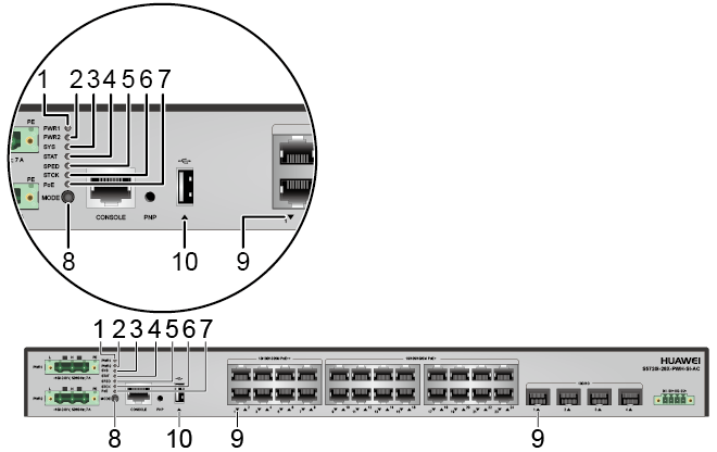
Indicator Description
- If the switch has no configuration file, the system attempts to enter the web initial login mode. In this mode, the status of mode indicators is as follows:
- If the system enters the web initial login mode successfully, all mode indicators turn green and stay on for a maximum of 10 minutes.
- If the system fails to enter the initial login mode, all mode indicators fast blink for 10 seconds and then restore the default status.
- If the switch has a configuration file, the system cannot enter the web initial login mode. In this case, all mode indicators fast blink for 10s, and then return to the default states.
The S5720I-SI series switches provide a command for setting fault indicators, which help field maintenance personnel find a faulty switch quickly.
The SYS indicator and mode indicators (STAT, SPED, STCK, and PoE) are used as fault indicators. When an S5720I-SI switch is faulty, you can run the command to turn on the fault indicators. Then the SYS indicator and mode indicators fast blink red to help field maintenance personnel quickly find the faulty switch.
No. |
Indicator |
Name |
Color |
Status |
Description |
|---|---|---|---|---|---|
1 |
PWR1 |
Power module indicator |
- |
Off |
No power module is available in power module slot 1, or the switch has only one power module but the power module does not work normally. |
Green |
Steady on |
A power module is installed in power module slot 1 and is working normally. |
|||
Yellow |
Steady on |
The switch has two power modules installed. Any of the following situations occurs in power module slot 1:
|
|||
2 |
PWR2 |
Power module indicator |
- |
Off |
No power module is available in power module slot 2, or the switch has only one power module but the power module does not work normally. |
Green |
Steady on |
A power module is installed in power module slot 2 and is working normally. |
|||
Yellow |
Steady on |
The switch has two power modules installed. Any of the following situations occurs in power module slot 2:
|
|||
3 |
SYS |
System status indicator |
- |
Off |
The system is not running. |
Green |
Fast blinking |
The system is starting. |
|||
Green |
Slow blinking |
The system is running normally. |
|||
Red |
Steady on |
The system does not work normally after registration, or a fan alarm or temperature alarm has been generated. |
|||
4 |
STAT |
Status indicator |
- |
Off |
The status mode is not selected. |
Green |
Steady on |
The status mode (default mode) is selected. If the status mode is selected, the service port indicator shows the port link or activity state. |
|||
5 |
SPED |
Speed indicator |
- |
Off |
The speed mode is not selected. |
Green |
Steady on |
The service port indicators show the port speeds. After 45 seconds, the service port indicators automatically restore to the status mode. |
|||
6 |
STCK |
Stack indicator |
- |
Off |
|
Green |
Steady on |
The switch is a standby or slave switch in a stack, and the service port indicators show the stack ID of the switch. |
|||
Green |
Blinking |
After 45 seconds, the service port indicators automatically restore to the status mode. |
|||
7 |
PoE |
PoE indicator |
- |
Off |
The PoE mode is not selected. |
Green |
Steady on |
The service port indicators show the PoE status. After 45 seconds, the service port indicators automatically restore to the status mode. |
|||
8 |
MODE |
Mode switch button |
- |
- |
If you do not press the MODE button within 45 seconds, the service port indicators restore to the default mode. In this case, the STAT indicator is steady green, the SPED and PoE indicators are off, and the STCK indicator is off or blinking green. |
9 |
- |
Service port indicator |
Meanings of service port indicators vary in different modes. For details, see Table 6. |
||
10 |
- |
USB-based deployment indicator |
- |
Off |
|
Green |
Steady on |
A USB-based deployment has been completed. |
|||
Green |
Blinking |
The system is reading data from the USB flash drive. |
|||
Yellow |
Steady on |
The switch has copied all the required files and completed the file check. The USB flash drive can be removed from the switch. |
|||
Red |
Blinking |
An error has occurred when the system is executing the configuration file or reading data from the USB flash drive. |
|||
| Display Mode | Color | Status | Description |
|---|---|---|---|
| Status | - | Off | The port is not connected or has been shut down. |
| Green | Steady on | A link has been established on the port. | |
| Green | Blinking | The port is sending or receiving data. | |
| Speed | - | Off | The port is not connected or has been shut down. |
| Green | Steady on | 10M/100M/1000M port: The port is operating at 10/100 Mbit/s. 1000M/10GE port: The port is operating at 1000 Mbit/s. |
|
| Green | Blinking | 10M/100M/1000M port: The port is operating at 1000 Mbit/s. 1000M/10GE port: The port is operating at 10 Gbit/s. |
|
| PoE | - | Off | The port is not providing power to a powered device (PD). |
| Green | Steady on | The port is providing power to a PD. | |
| Yellow | Steady on | The PoE function is disabled on the port. | |
| Yellow | Blinking | The port stops providing PoE power because of an exception (for example, an incompatible PD is connected to the port). | |
| Green and yellow | Blinking green and yellow alternately | The port fails to supply power to a PD due to one of the following
reasons:
|
|
| Stack | - | Off | Port indicators do not show the stack ID of the switch. |
| Green | Steady on | ||
| Green | Blinking |
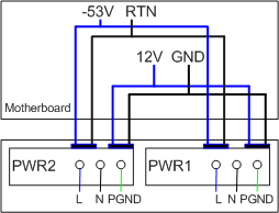
Power Supply Configuration
The S5720I-28X-PWH-SI-AC has two built-in power modules for 1+1 power redundancy and does not support pluggable power modules.
- High-power mode (default): When double power modules are used, they provide 369.6 W PoE power for the eight PoE++ ports and 369.6 W PoE power for the sixteen PoE+ ports (total of 739.2 W PoE power). When either of the two power modules fails, the eight PoE++ ports can supply power for PDs normally; however, the PDs connected to the sixteen PoE+ ports are powered off, and the PoE function is unavailable. When a single power module is used, only the eight PoE++ ports can supply PoE power for PDs.
- PoE backup mode: You can run the poe-power backup-mode command to manually switch the PoE power supply mode to the backup mode. In backup mode, the entire system provides 369.6 W PoE power regardless of whether a single power module or double power modules are used. That is, all 24 ports share the 369.6 W power. When double power modules are used, they work in 1+1 redundancy mode.
When the power supply mode is manually switched to the PoE backup mode, the PDs connected to all ports are powered off and then powered on again.
When the switch works in PoE backup mode, the PDs connected to all ports are powered off and then powered on again if the switch is restarted.
Power Supply Mode |
Power Supply Configuration |
Available PoE Power |
Maximum Number of Ports (Fully Loaded) |
|---|---|---|---|
High-power mode |
Single power module |
369.6 W |
Eight PoE++ ports:
Sixteen PoE+ ports: N/A |
Double power modules |
739.2 W |
Eight PoE++ ports:
Sixteen PoE+ ports:
|
|
PoE backup mode |
Single power module |
369.6 W |
Twenty-four ports:
|
Double power modules |
Heat Dissipation
The S5720I-28X-PWH-SI-AC has four built-in fans for forced air cooling. The airflow direction is left-to-right.
Technical Specifications
Table 8 lists technical specifications of the S5720I-28X-PWH-SI-AC.
Item |
Description |
|---|---|
Memory (RAM) |
512 MB |
Flash |
512 MB in total. To view the available flash memory size, run the display version command. |
Mean time between failures (MTBF) |
45.94 years |
Mean time to repair (MTTR) |
2 hours |
Availability |
> 0.99999 |
Service port surge protection |
±1.5 kV in differential mode, ±6 kV in common mode |
Power supply surge protection |
±6 kV in differential mode, ±6 kV in common mode |
Dimensions (H x W x D) |
43.6 mm x 442.0 mm x 310.0 mm (1.72 in. x 17.4 in. x 12.2 in.) |
Weight (with packaging) |
6.7 kg (14.77 lb) |
Stack ports |
Twenty-four 10/100/1000BASE-T ports and four 10G SFP+ ports |
RTC |
Supported |
RPS |
Not supported |
PoE |
Supported |
Rated voltage range |
100 V AC to 240 V AC, 50/60 Hz |
Maximum voltage range |
90 V AC to 264 V AC, 47 Hz to 63 Hz |
Maximum power consumption (100% throughput, full speed of fans) |
|
Typical power consumption (30% of traffic load)
|
34.6 W |
Operating temperature |
-40°C to +65°C (-40°F to +149°F) at an altitude of 0-1800 m (0-5906 ft.) NOTE:
When the altitude is 1800-5000 m (5906-16404 ft.), the highest operating temperature reduces by 1°C (1.8°F) every time the altitude increases by 220 m (722 ft.). |
Storage temperature |
-40°C to +85°C (-40°F to +185°F) |
Protection rating |
IP20 |
Noise under normal temperature (27°C, sound power) |
< 47 dB(A) |
Relative humidity |
5% to 95%, noncondensing |
Operating altitude |
0-5000 m (0-16404 ft.) |
Certification |
|
Part number |
98010797 |