Information Advertisement
MPLS TE uses a routing protocol to advertise information about resources allocated to network nodes. Each node on an MPLS TE network, especially the ingress node, determines the path of a tunnel according to the advertised information.
What Information Is Advertised
Link information: includes interface IP addresses, link types, and link metrics, which are collected by an IGP.
Bandwidth information: includes the maximum link bandwidth, maximum reservable bandwidth, and available bandwidth corresponding to each link priority.
TE metric: indicates the metric value of a link. By default, IGP metric is used as TE metric.
Link administrative group: indicates the color of a link.
Affinity attribute: indicates the link colors required for a TE tunnel.
Shared risk link group (SRLG): is a constraint for path calculation, which prevents the backup path of a tunnel from being set up on links with the same risk level as the primary path.
How Information Is Advertised
TE information is advertised using extensions of link-state routing protocols: OSPF TE and IS-IS TE. The Open Shortest Path First (OSPF) and Intermediate System to Intermediate System (IS-IS) protocols collect TE information on a node and flood the collected information to other nodes on the MPLS TE network.
OSPF is a link state routing protocol that supports flexible extensions. It defines link-state advertisements (LSAs) of Type-1 to Type-5 and Type-7 to carry inter-area, intra-area, and autonomous system (AS) external routing information. Formats of these LSAs do not meet the requirements of MPLS TE; therefore, two extended LSAs, Opaque LSA and TE LSA, are defined to implement MPLS TE.
Opaque LSA
Opaque LSAs include Type-9, Type-10, and Type-11 LSAs. Type-9 LSAs can only be flooded to the local network connected to an interface, and Type-10 LSAs can only be flooded to the local area. Type-11 LSAs are similar to Type-5 LSAs and can be flooded to the local AS except stub areas and not-so-stubby areas (NSSAs).
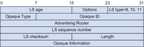
An Opaque LSA has the same header format as the other types of LSAs, except that the four-byte Link State ID field is divided into an Opaque Type field and an Opaque ID field, as shown in Figure 1.
The Opaque Type field is the leftmost byte that identifies the application type of an Opaque LSA. The Opaque ID field is the rightmost three bytes that differentiate LSAs of the same type. Therefore, each type of Opaque LSA has 255 applications, and each application has 16777216 different LSAs within a flooding scope.
For example, OSPF Graceful Restart LSAs are Type-9 LSAs with the Opaque Type of 3, and TE LSAs are Type-10 LSAs with the Opaque Type of 1.
The Opaque Information field contains the content to be advertised by an LSA. The information format is defined by the specific application. The commonly used format is the extensible Type/Length/Value (TLV) structure.
Figure 2 TLV structure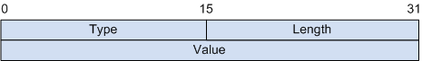
Type: indicates the type of information carried in the TLV.
Length: indicates the number of bytes in the Value field.
Value: indicates information carried in the TLV. This field can be another TLV (sub-TLV).
TE LSA
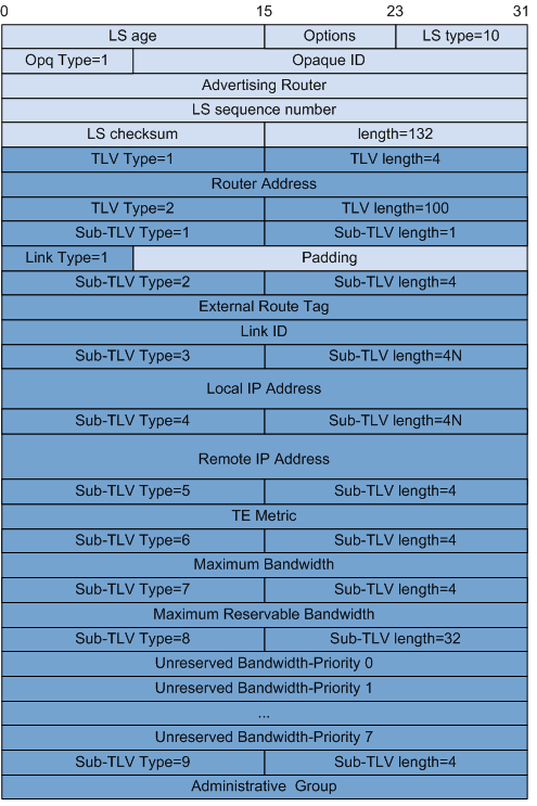
TE LSAs are Type-10 LSAs applied to TE. The Opaque Type of TE LSAs is 1. Therefore, TE LSAs have a link state ID of 1.x.x.x and are flooded within an area. Figure 3 shows the TE LSA structure.
TE LSAs carry information in TLVs. Two types of TLVs are defined for TE LSAs:
TLV Type 1
It is a Router Address TLV that uniquely identifies an MPLS node. A Router Address TLV plays the same role as a router ID in the Constrained Shortest Path First (CSPF) algorithm.
TLV Type 2
It is a Link TLV that carries attributes of an MPLS TE capable link. Table 1 lists the sub-TLVs that can be carried in a Link TLV.
Table 1 Sub-TLVs in a Link TLV Sub-TLV
Description
Type 1: Link Type (with a 1-byte Value field)
Carries a link type.1: point-to-point link
2: multi-access link
The Value field of this sub-TLV is followed by a 3-byte padding field.
Type 2: Link ID (with a 4-byte Value field)
Carries a link identifier in IP address format.For a point-to-point link, this sub-TLV indicates the OSPF router ID of a neighbor.
For a multi-access link, this sub-TLV indicates the interface IP address of the designated router (DR).
Type 3: Local IP Address (with a 4N-byte Value field)
Carries one or more local interface IP addresses. Each IP address occupies 4 bytes.
Type 4: Remote IP Address (with a 4N-byte Value field)
Carries one or more remote interface IP addresses. Each IP address occupies 4 bytes.For a point-to-point link, this sub-TLV is filled with a remote IP address.
For a multi-access link, this sub-TLV is filled with 0.0.0.0 or is not carried in the TLV.
Type 5: Traffic Engineering Metric (with a 4-byte Value field)
Carries the TE metric configured on a TE link. The data format is ULONG.
Type 6: Maximum Bandwidth (with a 4-byte Value field)
Carries the maximum bandwidth of a link. The value is a 4-byte floating point number.
Type 7: Maximum Reservable Bandwidth (with a 4-byte Value field)
Carries the maximum reservable bandwidth of a link. The value is a 4-byte floating point number.
Type 8: Unreserved Bandwidth (with a 32-byte Value field)
Carries reservable bandwidth values for the eight priorities of a link. The bandwidth for each priority is a 4-byte floating point number.
Type 9: Administrative Group (with a 4-byte Value field)
Carries the administrative group attribute of a link.
If an OSPF-capable link that has established an OSPF neighbor relationship is identified as an MPLS TE link, OSPF TE generates a TE LSA carrying information about the MPLS TE link and advertises the TE LSA to the local area. If other nodes in the local area support TE extensions, these nodes establish a topology of TE links. Each node that advertises TE LSAs must have a unique router address.
Type-10 Opaque LSAs are advertised within an OSPF, so CSPF calculation is performed on an area basis. To calculate an LSP spanning multiple areas, CSPF calculation must be performed in each area.
IS-IS is a link state routing protocol and supports TE extensions to advertise TE information.
IS-IS TE defines two new TLV types:
Type 135: Wide Metric
IS-IS has two metrics:
Narrow metric: 6 bits
Wide metric: 32 bits. Wide Metric TLVs are only used to transmit TE information and cannot be used for route calculation.
A Narrow Metric TLV supports only 64 vector values and cannot meet traffic engineering requirements on large-scale networks. Wide Metric TLVs are more suitable for TE information advertisement.
To allow for the transition from Narrow Metric to Wide Metric, IS-IS TE defines the following vector values:
Compatible: allows a device to send and receive packets with narrow and wide metrics.
Wide Compatible: allows a device to receive packets with narrow and wide metrics but to send only packets with wide metrics.
Type 22: IS Reachability TLV
Figure 4 shows the format of an IS Reachability TLV.
An IS Reachability TLV consists of the following:
System ID and pseudo node ID
Default link metric
Length of sub-TLVs
Variable-length sub-TLVs
Table 2 describes sub-TLVs in an IS Reachability TLV.
Table 2 Sub-TLVs in an IS Reachability TLV Sub-TLV
Description
Type 3: Administrative group (with a 4-byte Value field)
Indicates the administrative attribute of a link. The 32 bits in the attribute represent 32 administrative groups.
Type 6: IPv4 interface address (with a 4N-byte Value field)
Carries one or more local interface IP addresses. Each IP address occupies 4 bytes.
Type 8: IPv4 neighbor address (with a 4N-byte Value field)
Indicates one or more remote interface IP addresses. Each IP address occupies 4 bytes.For a point-to-point link, this sub-TLV is filled with a remote IP address.
For a multi-access link, this sub-TLV is filled with 0.0.0.0.
Type 9: Maximum link bandwidth (with a 4-byte Value field)
Carries the maximum bandwidth of a link.
Type 10: Reservable link bandwidth (with a 4-byte Value field)
Carries the maximum reservable bandwidth of a link.
Type 11: Unreserved bandwidth (with a 32-byte Value field)
Carries reservable bandwidth for eight priorities of a link.
Type 18: TE Default metric (with a 3-byte Value field)
Carries the TE metric configured on a TE link.

When Information Is Advertised
To maintain a uniform traffic engineering database (TEDB) in an area, OSPF TE and IS-IS TE must flood the area with link information. Besides configuration of a new MPLS TE tunnel, the following conditions can trigger TE information flooding:
The IGP TE flooding interval expires. (The flooding interval is configurable.)
A link is activated or fails.
An LSP cannot be set up because of insufficient bandwidth. In this case, the local node immediately floods the current available link bandwidth in the area.
Link attributes, such as the administrative group and affinity attributes, change.
The link bandwidth changes.
When the available bandwidth of an MPLS interface changes, the local node updates TEDB and floods the updated link information. If a node needs to reserve bandwidth for a large number of tunnels to be set up, the system frequently updates the TEDB and triggers flooding. For example, if 100 tunnels with 1 Mbit/s bandwidth need to be set up on a 100 Mbit/s link, the system needs to flood link information 100 times.
MPLS TE uses a bandwidth flooding mechanism to reduce the frequency of TEDB updating and flooding. When either of the following conditions is met, an IGP floods link information and updates the TEDB:
The ratio between bandwidth reserved for an MPLS TE tunnel on a link and available link bandwidth in the TEDB is greater than or equal to the configured threshold.
The ratio between bandwidth released from an MPLS TE tunnel and available link bandwidth in the TEDB is greater than or equal to the configured threshold.
Assume that available bandwidth of a link is 100 Mbit/s. If 100 MPLS TE tunnels with 1 Mbit/s bandwidth need to be set up on the link and the flooding threshold is 10%, the ratios between reserved bandwidth and available bandwidth and the flooding process are shown in Figure 5.
The system does not flood bandwidth information when creating tunnels 1 to 9. When tunnel 10 is created, the system floods the 10 Mbit/s bandwidth occupied by the 10 tunnels. The available bandwidth is now 90 Mbit/s. Similarly, the system does not flood bandwidth information when creating tunnels 11 to 18, and it does not flood bandwidth information until tunnel 19 is created. The other flooding processes can be deducted by analogy.

Information Advertisement Result
After an OSPF TE or IS-IS TE flooding process is complete, all nodes in the local area generate the same TEDB.
Nodes on an MPLS TE network need to advertise resource information. Each device collects link information in the local area, such as constraints and bandwidth usage, and generates a database of link attributes and topology attributes. This database is the TEDB.
A device calculates the optimal path to another node in the local area according to information in the TEDB. MPLS TE then uses this path to set up a CR-LSP.
The TEDB is independent of the link state database (LSDB) of an IGP. Both the two databases are generated through IGP-based flooding, but they record different information and provide different functions. The TEDB stores TE information in addition to all information available in the LSDB. The LSDB is used to calculate the shortest path, whereas the TEDB is used to calculate the best LSP for an MPLS TE tunnel.