Example for Configuring Bit-Error-Triggered RSVP-TE Tunnel Switching
This section provides an example for configuring bit-error-triggered Resource Reservation Protocol-Traffic Engineering (RSVP-TE) tunnel switching.
Networking Requirements
In a scenario in which a bidirectional RSVP-TE tunnel (consisting of a pair of unidirectional tunnels) with traffic engineering (TE) hot standby protection is deployed between two nodes, you can configure bit-error-triggered RSVP-TE tunnel switching to protect services against bit errors.
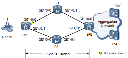
On the network shown in Figure 1, a bidirectional RSVP-TE tunnel with TE hot standby protection needs to be deployed between the user-end provider edge (UPE) and superstratum provider edge (SPE). The primary and backup constraint-based routed label switched paths (CR-LSPs) of the bidirectional RSVP-TE tunnel are UPE <-> P1 <-> SPE and UPE <-> P2 <-> SPE, respectively. In normal circumstances, traffic between the UPE and SPE travels along the primary CR-LSP UPE <-> P1 <-> SPE. If a bit error event occurs on GE0/1/0 of the UPE, traffic traveling along the primary CR-LSP is affected. To resolve this problem, configure bit-error-triggered RSVP-TE tunnel switching to enable the bidirectional RSVP-TE tunnel to switch traffic to the backup CR-LSP if a bit error event occurs on the primary CR-LSP.

The thresholds for bit-error-triggered protection switching and revertive switching can be configured. If the total bit error rate (BER) of the primary CR-LSP exceeds the threshold for bit-error-triggered protection switching, the bidirectional RSVP-TE tunnel determines whether to perform a primary/backup CR-LSP switchover. The bidirectional RSVP-TE tunnel performs a primary/backup CR-LSP switchover if the backup CR-LSP is in the normalized BER state. If the primary and backup CR-LSPs are both in the excessive BER state, traffic still travels along the primary CR-LSP. In actual situations, configure the thresholds for bit-error-triggered protection switching and revertive switching based on the sensitivity of services to bit errors.
In addition, the primary and backup CR-LSPs are both in the excessive BER state, traffic still travels along the primary CR-LSP.
Configuration Roadmap
The configuration roadmap is as follows:
Configure an IP address and a routing protocol for each interface so that all nodes can communicate at the network layer. This example uses Open Shortest Path First (OSPF) as the routing protocol.
Enable Bidirectional Forwarding Detection (BFD) globally on each node.
Configure a bidirectional RSVP-TE tunnel with TE hot standby protection between the UPE and SPE.
Configure BFD for CR-LSP for the bidirectional RSVP-TE tunnel.
Enable bit-error-triggered RSVP-TE tunnel switching for the bidirectional RSVP-TE tunnel and set the thresholds for bit-error-triggered protection switching and revertive switching.
On each tunnel interface, specify the other unidirectional tunnel as the reverse tunnel of the current unidirectional tunnel.

Before establishing a unidirectional RSVP-TE tunnel, you must run the label advertise non-null command to enable the egress of the unidirectional tunnel to allocate a non-null label to the penultimate hop. Otherwise, bit-error-triggered RSVP-TE tunnel switching cannot take effect.
Data Preparation
To complete the configuration, you need the following data:
Interface IP addresses (see Figure 1)
OSPF process ID (100) and area ID (0.0.0.0)
Multiprotocol Label Switching (MPLS) label switching router (LSR) IDs (Loopback0 interface IP addresses) of each node
Tunnel interface names (Tunnel10), tunnel IDs (100), and explicit path names of the primary and backup CR-LSPs (main path and hsb-path)
Thresholds for triggering bit-error-triggered protection switching and revertive switching (3e-4 and 2e-5)
Procedure
- Configure interface IP addresses.
Assign an IP address to each interface according to Figure 1 and create a loopback interface on each node. For configuration details, see Configuration Files in this section.
- Configure OSPF.
Configure OSPF on each node to allow the nodes to communicate at the network layer. For configuration details, see Configuration Files in this section.
- Enable MPLS, MPLS TE, RSVP-TE, and Constraint Shortest Path First (CSPF) on nodes along the primary and backup CR-LSPs of the bidirectional RSVP-TE tunnel to be created.
For configuration details, see Configuration Files in this section.
- Enable BFD globally.
# Configure the UPE.
<UPE> system-view
[~UPE] bfd
[*UPE-bfd] commit
[~UPE-bfd] quit
Repeat this step for P1, PE2, and the SPE.
- Configure the egress of each unidirectional RSVP-TE tunnel to be created to assign a non-null label to the penultimate hop.
# Configure the UPE (egress for the unidirectional RSVP-TE tunnel from the SPE to the UPE).
[~UPE] mpls
[~UPE-mpls] label advertise non-null
[*UPE-mpls] commit
[~UPE-mpls] quit
# Configure the SPE (egress for the unidirectional RSVP-TE tunnel from the UPE to the SPE).
[~SPE] mpls
[~SPE-mpls] label advertise non-null
[*SPE-mpls] commit
[~SPE-mpls] quit
- Configure explicit paths.
# Configure the UPE.
[~UPE] explicit-path main-path
[*UPE-explicit-path-main-path] next hop 10.1.1.2
[*UPE-explicit-path-main-path] next hop 10.1.3.2
[*UPE-explicit-path-main-path] commit
[~UPE-explicit-path-main-path] quit
[~UPE] explicit-path hsb-path
[*UPE-explicit-path-hsb-path] next hop 10.1.2.2
[*UPE-explicit-path-hsb-path] next hop 10.1.4.2
[*UPE-explicit-path-hsb-path] commit
[~UPE-explicit-path-hsb-path] quit
# Configure the SPE.
[~SPE] explicit-path main-path
[*SPE-explicit-path-main-path] next hop 10.1.3.1
[*SPE-explicit-path-main-path] next hop 10.1.1.1
[*SPE-explicit-path-main-path] commit
[~SPE-explicit-path-main-path] quit
[~SPE] explicit-path hsb-path
[*SPE-explicit-path-hsb-path] next hop 10.1.4.1
[*SPE-explicit-path-hsb-path] next hop 10.1.2.1
[*SPE-explicit-path-hsb-path] commit
[~SPE-explicit-path-hsb-path] quit
- Establish a bidirectional RSVP-TE tunnel with TE hot standby protection.
# Configure the UPE.
[~UPE] interface Tunnel10
[*UPE-Tunnel10] ip address unnumbered interface loopback 0
[*UPE-Tunnel10] tunnel-protocol mpls te
[*UPE-Tunnel10] destination 4.4.4.4
[*UPE-Tunnel10] mpls te tunnel-id 100
[*UPE-Tunnel10] mpls te path explicit-path main-path
[*UPE-Tunnel10] mpls te backup hot-standby
[*UPE-Tunnel10] mpls te path explicit-path hsb-path secondary
[*UPE-Tunnel10] commit
# Configure the SPE.
[~SPE] interface Tunnel10
[*SPE-Tunnel10] ip address unnumbered interface loopback 0
[*SPE-Tunnel10] tunnel-protocol mpls te
[*SPE-Tunnel10] destination 1.1.1.1
[*SPE-Tunnel10] mpls te tunnel-id 100
[*SPE-Tunnel10] mpls te path explicit-path main-path
[*SPE-Tunnel10] mpls te backup hot-standby
[*SPE-Tunnel10] mpls te path explicit-path hsb-path secondary
[*SPE-Tunnel10] commit
- Configure dynamic BFD for CR-LSP.
# Configure the UPE.
[~UPE-Tunnel10] mpls te bfd enable
[*UPE-Tunnel10] quit
[*UPE] bfd
[*UPE-bfd] mpls-passive
[*UPE-bfd] quit
[*UPE] commit
# Configure the SPE.
[~SPE-Tunnel10] mpls te bfd enable
[*SPE-Tunnel10] quit
[*SPE] bfd
[*SPE-bfd] mpls-passive
[*SPE-bfd] quit
[*SPE] commit
- Enable bit-error-triggered RSVP-TE tunnel switching and set the thresholds for bit-error-triggered protection switching and revertive switching.
# Configure the UPE.
[~UPE] interface Tunnel10
[~UPE-Tunnel10] mpls te bit-error-detection
[*UPE-Tunnel10] mpls te bit-error-detection threshold switch 3 4 resume 2 5
[*UPE-Tunnel10] commit
# Configure the SPE.
[~SPE] interface Tunnel10
[~SPE-Tunnel10] mpls te bit-error-detection
[*SPE-Tunnel10] mpls te bit-error-detection threshold switch 3 4 resume 2 5
[*SPE-Tunnel10] commit
- Specify the reverse tunnel for each unidirectional RSVP-TE tunnel.
# Configure the UPE.
[~UPE-Tunnel10] mpls te reverse-lsp protocol rsvp-te ingress-lsr-id 4.4.4.4 tunnel-id 100
[*UPE-Tunnel10] commit
[~UPE-Tunnel10] quit
# Configure the SPE.
[~SPE-Tunnel10] mpls te reverse-lsp protocol rsvp-te ingress-lsr-id 1.1.1.1 tunnel-id 100
[*SPE-Tunnel10] commit
[~SPE-Tunnel10] quit
- Verify the configuration.
In this example, the BER detected by GE 0/1/0 on the UPE exceeding the threshold for triggering an alarm indicating that a bit error event has occurred. As a result, GE 0/1/0 goes Down. If the total BER of the primary CR-LSP exceeds the threshold for bit-error-triggered protection switching, the bidirectional RSVP-TE tunnel between the UPE and SPE switches to the backup CR-LSP.
# Run the display mpls te tunnel bit-error-detection command on the UPE and SPE. The command output shows the CR-LSP bit error status and BER information.
[~UPE] display mpls te tunnel bit-error-detection
BED-Rate(R/L): R - Remote BFD Session, L - Local BFD Session
-------------------------------------------------------------------------------
LSP-ID                       LSP-Type    BED-State     BED-Rate(R/L)     Tunnel-name
-------------------------------------------------------------------------------
4.4.4.4:100:1                Primary     --                   9e-1/0     Tunnel10
4.4.4.4:100:2                Hot-Standby --                      0/0     Tunnel10
1.1.1.1:100:22               Primary     Start                9e-1/0     Tunnel10
1.1.1.1:100:23               Hot-Standby Stop                    0/0     Tunnel10
[~SPE] display mpls te tunnel bit-error-detection
BED-Rate(R/L): R - Remote BFD Session, L - Local BFD Session
-------------------------------------------------------------------------------
LSP-ID                       LSP-Type    BED-State     BED-Rate(R/L)     Tunnel-name
-------------------------------------------------------------------------------
4.4.4.4:100:1                Primary     Start                0/9e-1     Tunnel10
4.4.4.4:100:2                Hot-Standby Stop                    0/0     Tunnel10
1.1.1.1:100:22               Primary     --                   0/9e-1     Tunnel10
1.1.1.1:100:23               Hot-Standby --                      0/0     Tunnel10
# Run the display mpls te hot-standby state all command on the UPE and SPE. The command output shows the primary/backup CR-LSP switchover result.
[~UPE] display mpls te hot-standby state all
----------------------------------------------------------------------
No.        tunnel name                    session id   switch-result
----------------------------------------------------------------------
1          Tunnel10                    100          hot-standby LSP
[~SPE] display mpls te hot-standby state all
----------------------------------------------------------------------
No.        tunnel name                    session id   switch-result
----------------------------------------------------------------------
1          Tunnel10                    100          hot-standby LSP
Configuration Files
Configuration file of the UPE
#
sysname UPE
#
bfd
 mpls-passive
#
mpls lsr-id 1.1.1.1
#
mpls
 label advertise non-null
 mpls te
 mpls rsvp-te
 mpls te cspf
#
explicit-path main-path
 next hop 10.1.1.2
 next hop 10.1.3.2
#
explicit-path hsb-path
 next hop 10.1.2.2
 next hop 10.1.4.2
#
interface GigabitEthernet0/1/0
 undo shutdown
 ip address 10.1.1.1 255.255.255.0
 mpls
 mpls te
 mpls rsvp-te

#
interface GigabitEthernet0/1/1
 undo shutdown
 ip address 10.1.2.1 255.255.255.0
 mpls
 mpls te
 mpls rsvp-te

#
interface LoopBack0
 ip address 1.1.1.1 255.255.255.255
#
interface Tunnel10
 ip address unnumbered interface LoopBack0
 tunnel-protocol mpls te
 destination 4.4.4.4
 mpls te record-route
 mpls te backup hot-standby
 mpls te bit-error-detection
 mpls te bit-error-detection threshold switch 3 4 resume 2 5
 mpls te reverse-lsp protocol rsvp-te ingress-lsr-id 4.4.4.4 tunnel-id 100
 mpls te tunnel-id 100
 mpls te bfd enable
 mpls te path explicit-path main-path
 mpls te path explicit-path hsb-path secondary
#
ospf 100
 opaque-capability enable
 area 0.0.0.0
  network 1.1.1.1 0.0.0.0
  network 10.1.1.0 0.0.0.255
  network 10.1.2.0 0.0.0.255
  mpls-te enable
#
return
Configuration file of P1
#
sysname P1
#
bfd
#
mpls lsr-id 2.2.2.2
#
mpls
 mpls te
 mpls rsvp-te
 mpls te cspf
#
interface GigabitEthernet0/1/0
 undo shutdown
 ip address 10.1.1.2 255.255.255.0
 mpls
 mpls te
 mpls rsvp-te

#
interface GigabitEthernet0/1/1
 undo shutdown
 ip address 10.1.3.1 255.255.255.0
 mpls
 mpls te
 mpls rsvp-te

#
interface LoopBack0
 ip address 2.2.2.2 255.255.255.255
#
ospf 100
 opaque-capability enable
 area 0.0.0.0
  network 2.2.2.2 0.0.0.0
  network 10.1.1.0 0.0.0.255
  network 10.1.3.0 0.0.0.255
  mpls-te enable
#
return
Configuration file of P2
#
sysname P2
#
bfd
#
mpls lsr-id 3.3.3.3
#
mpls
 mpls te
 mpls rsvp-te
 mpls te cspf
#
interface GigabitEthernet0/1/0
 undo shutdown
 ip address 10.1.2.2 255.255.255.0
 mpls
 mpls te
 mpls rsvp-te

#
interface GigabitEthernet0/1/1
 undo shutdown
 ip address 10.1.4.1 255.255.255.0
 mpls
 mpls te
 mpls rsvp-te

#
interface LoopBack0
 ip address 3.3.3.3 255.255.255.255
#
ospf 100
 opaque-capability enable
 area 0.0.0.0
  network 3.3.3.3 0.0.0.0
  network 10.1.2.0 0.0.0.255
  network 10.1.4.0 0.0.0.255
  mpls-te enable
#
return
Configuration file of the SPE
#
sysname SPE
#
bfd
 mpls-passive
#
mpls lsr-id 4.4.4.4
#
mpls
 label advertise non-null
 mpls te
 mpls rsvp-te
 mpls te cspf
#
explicit-path main-path
 next hop 10.1.3.1
 next hop 10.1.1.1
#
explicit-path hsb-path
 next hop 10.1.4.1
 next hop 10.1.2.1
#
interface GigabitEthernet0/1/0
 undo shutdown
 ip address 10.1.3.2 255.255.255.0
 mpls
 mpls te
 mpls rsvp-te

#
interface GigabitEthernet0/1/1
 undo shutdown
 ip address 10.1.4.2 255.255.255.0
 mpls
 mpls te
 mpls rsvp-te

#
interface LoopBack0
 ip address 4.4.4.4 255.255.255.255
#
interface Tunnel10
 ip address unnumbered interface LoopBack0
 tunnel-protocol mpls te
 destination 1.1.1.1
 mpls te record-route
 mpls te backup hot-standby
 mpls te bit-error-detection
 mpls te bit-error-detection threshold switch 3 4 resume 2 5
 mpls te reverse-lsp protocol rsvp-te ingress-lsr-id 1.1.1.1 tunnel-id 100
 mpls te tunnel-id 100
 mpls te bfd enable
 mpls te path explicit-path main-path
 mpls te path explicit-path hsb-path secondary
#
ospf 100
 opaque-capability enable
 area 0.0.0.0
  network 4.4.4.4 0.0.0.0
  network 10.1.3.0 0.0.0.255
  network 10.1.4.0 0.0.0.255
  mpls-te enable
#
return