Example for Configuring EVPN L3VPNv6 over SR-MPLS TE
This section provides an example for configuring EVPN L3VPNv6 to iterate traffic over an SR-MPLS TE tunnel.
Networking Requirements
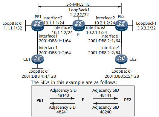
On the network shown in Figure 1, EVPN L3VPNv6 is configured on the backbone network to allow IPv6 interworking at Layer 3 between CEs. In this example, PEs transmit service traffic over SR-MPLS TE tunnels.
Configuration Notes
When configuring EVPN L3VPNv6 over SR-MPLS TE, note the following:
For the same VPN instance, the export VPN target list of a site shares VPN targets with the import VPN target lists of the other sites, and the import VPN target list of a site shares VPN targets with the export VPN target lists of the other sites.
Using the local loopback interface address of a PE as the EVPN source address is recommended.
Configuration Roadmap
The configuration roadmap is as follows:
Procedure
- Configure interface IP addresses of each device.
# Configure PE1.
<HUAWEI> system-view
[~HUAWEI] sysname PE1
[*HUAWEI] commit
[~PE1] interface loopback 1
[*PE1-LoopBack1] ip address 1.1.1.1 32
[*PE1-LoopBack1] quit
[*PE1] interface gigabitethernet0/1/8
[*PE1-GigabitEthernet0/1/8] ip address 10.1.1.1 24
[*PE1-GigabitEthernet0/1/8] quit
[*PE1] commit
# Configure P.
<HUAWEI> system-view
[~HUAWEI] sysname P
[*HUAWEI] commit
[~P] interface loopback 1
[*P-LoopBack1] ip address 2.2.2.2 32
[*P-LoopBack1] quit
[*P] interface gigabitethernet0/1/0
[*P-GigabitEthernet0/1/0] ip address 10.1.1.2 24
[*P-GigabitEthernet0/1/0] quit
[*P] interface gigabitethernet0/1/8
[*P-GigabitEthernet0/1/8] ip address 10.2.1.1 24
[*P-GigabitEthernet0/1/8] quit
[*P] commit
# Configure PE2.
<HUAWEI> system-view
[~HUAWEI] sysname PE2
[*HUAWEI] commit
[~PE2] interface loopback 1
[*PE2-LoopBack1] ip address 3.3.3.3 32
[*PE2-LoopBack1] quit
[*PE2] interface gigabitethernet0/1/8
[*PE2-GigabitEthernet0/1/8] ip address 10.2.1.2 24
[*PE2-GigabitEthernet0/1/8] quit
[*PE2] commit
- Configure an IGP to allow communication between PE1, PE2, and P. IS-IS is used as an IGP protocol in this example.
# Configure PE1.
[~PE1] isis 1
[*PE1-isis-1] is-level level-2
[*PE1-isis-1] network-entity 00.1111.1111.1111.00
[*PE1-isis-1] quit
[*PE1] interface loopback 1
[*PE1-LoopBack1] isis enable 1
[*PE1-LoopBack1] quit
[*PE1] interface GigabitEthernet 0/1/8
[*PE1-GigabitEthernet0/1/8] isis enable 1
[*PE1-GigabitEthernet0/1/8] quit
[*PE1] commit
# Configure the P.
[~P] isis 1
[*P-isis-1] is-level level-2
[*P-isis-1] network-entity 00.1111.1111.2222.00
[*P-isis-1] quit
[*P] interface loopback 1
[*P-LoopBack1] isis enable 1
[*P-LoopBack1] quit
[*P] interface GigabitEthernet 0/1/0
[*P-GigabitEthernet0/1/0] isis enable 1
[*P-GigabitEthernet0/1/0] quit
[*P] interface GigabitEthernet 0/1/8
[*P-GigabitEthernet0/1/8] isis enable 1
[*P-GigabitEthernet0/1/8] quit
[*P] commit
# Configure PE2.
[~PE2] isis 1
[*PE2-isis-1] is-level level-2
[*PE2-isis-1] network-entity 00.1111.1111.3333.00
[*PE2-isis-1] quit
[*PE2] interface loopback 1
[*PE2-LoopBack1] isis enable 1
[*PE2-LoopBack1] quit
[*PE2] interface GigabitEthernet 0/1/8
[*PE2-GigabitEthernet0/1/8] isis enable 1
[*PE2-GigabitEthernet0/1/8] quit
[*PE2] commit
After completing the configurations, run the display isis peer command to check that the status of the IS-IS neighbor relationship between PE1, PE2, and the P is Up. Run the display ip routing-table command to view that the PEs have learned the routes to Loopback1 of each other.
The following example uses the command output on PE1.
[~PE1] display isis peer
                          Peer information for ISIS(1)

  System Id     Interface         Circuit Id         State HoldTime Type     PRI
--------------------------------------------------------------------------------
1111.1111.2222  GE0/1/8           1111.1111.2222.02  Up    7s       L2       64

Total Peer(s): 1
[~PE1] display ip routing-table
Route Flags: R - relay, D - download to fib, T - to vpn-instance, B - black hole route
------------------------------------------------------------------------------
Routing Table : _public_
         Destinations : 11       Routes : 11

Destination/Mask    Proto   Pre  Cost        Flags NextHop         Interface

        1.1.1.1/32  Direct  0    0             D   127.0.0.1       LoopBack1
        2.2.2.2/32  ISIS-L2 15   10            D   10.1.1.2        GigabitEthernet0/1/8
        3.3.3.3/32  ISIS-L2 15   20            D   10.1.1.2        GigabitEthernet0/1/8
       10.1.1.0/24  Direct  0    0             D   10.1.1.1        GigabitEthernet0/1/8
       10.1.1.1/32  Direct  0    0             D   127.0.0.1       GigabitEthernet0/1/8
     10.1.1.255/32  Direct  0    0             D   127.0.0.1       GigabitEthernet0/1/8
       10.2.1.0/24  ISIS-L2 15   20            D   10.1.1.2        GigabitEthernet0/1/8
      127.0.0.0/8   Direct  0    0             D   127.0.0.1       InLoopBack0
      127.0.0.1/32  Direct  0    0             D   127.0.0.1       InLoopBack0
127.255.255.255/32  Direct  0    0             D   127.0.0.1       InLoopBack0
255.255.255.255/32  Direct  0    0             D   127.0.0.1       InLoopBack0
- Configure an SR-MPLS TE tunnel on the backbone network.
# Configure PE1.
[~PE1] mpls lsr-id 1.1.1.1
[*PE1] mpls
[*PE1-mpls] mpls te
[*PE1-mpls] quit
[*PE1] segment-routing
[*PE1-segment-routing] quit
[*PE1] isis 1
[*PE1-isis-1] cost-style wide
[*PE1-isis-1] traffic-eng level-2
[*PE1-isis-1] segment-routing mpls
[*PE1-isis-1] segment-routing global-block 153616 153800

The value range of SRGB varies according to the actual situation. This is only an example.
[*PE1-isis-1] quit
[*PE1] interface loopback 1
[*PE1-LoopBack1] isis prefix-sid absolute 153700
[*PE1-LoopBack1] quit
[*PE1] explicit-path pe1tope2
[*PE1-explicit-path-pe1tope2] next sid label 48140 type adjacency
[*PE1-explicit-path-pe1tope2] next sid label 48141 type adjacency
[*PE1-explicit-path-pe1tope2] quit
[*PE1] interface tunnel1
[*PE1-Tunnel1] ip address unnumbered interface loopback 1
[*PE1-Tunnel1] tunnel-protocol mpls te
[*PE1-Tunnel1] destination 3.3.3.3
[*PE1-Tunnel1] mpls te tunnel-id 1
[*PE1-Tunnel1] mpls te signal-protocol segment-routing
[*PE1-Tunnel1] mpls te path explicit-path pe1tope2
[*PE1-Tunnel1] mpls te reserved-for-binding
[*PE1-Tunnel1] quit
[*PE1] commit
The next sid label command uses the adjacency label from PE1 to P which is dynamically generated using IS-IS. This adjacency label can be obtained using the display segment-routing adjacency mpls forwarding command.
[~PE1] display segment-routing adjacency mpls forwarding
            Segment Routing Adjacency MPLS Forwarding Information

Label     Interface         NextHop          Type        MPLSMtu   Mtu
-----------------------------------------------------------------------------
48140     GE0/1/8           10.1.1.2         ISIS-V4     ---       1500
# Configure the P.
[~P] mpls lsr-id 2.2.2.2
[*P] mpls
[*P-mpls]  mpls te
[*P-mpls] quit
[*P] segment-routing
[*P-segment-routing] quit
[*P] isis 1
[*P-isis-1] cost-style wide
[*P-isis-1] traffic-eng level-2
[*P-isis-1] segment-routing mpls
[*P-isis-1] segment-routing global-block 153616 153800
The value range of SRGB changes dynamically, depending on the actual situation of the equipment. Here is an example only.
[*P-isis-1] quit
[*P] interface loopback 1
[*P-LoopBack1] isis prefix-sid absolute 153710
[*P-LoopBack1] quit
[*P] commit
After the configuration is complete, yan can view the adjacency labels by using the display segment-routing adjacency mpls forwarding command.
[~P] display segment-routing adjacency mpls forwarding
            Segment Routing Adjacency MPLS Forwarding Information

Label     Interface         NextHop          Type        MPLSMtu   Mtu
-----------------------------------------------------------------------------
48241     GE0/1/0           10.1.1.1         ISIS-V4     ---       1500
48140     GE0/1/8           10.2.1.2         ISIS-V4     ---       1500
# Configure PE2.
[~PE2] mpls lsr-id 3.3.3.3
[*PE2] mpls
[*PE2-mpls] mpls te
[*PE2-mpls] quit
[*PE2] segment-routing
[*PE2-segment-routing] quit
[*PE2] isis 1
[*PE2-isis-1] cost-style wide
[*PE2-isis-1] traffic-eng level-2
[*PE2-isis-1] segment-routing mpls
[*PE2-isis-1] segment-routing global-block 153616 153800
The value range of SRGB changes dynamically, depending on the actual situation of the equipment. Here is an example only.
[*PE2-isis-1] quit
[*PE2] interface loopback 1
[*PE2-LoopBack1] isis prefix-sid absolute 153720
[*PE2-LoopBack1] quit
[*PE2] explicit-path pe2tope1
[*PE2-explicit-path-pe2tope1] next sid label 48240 type adjacency
[*PE2-explicit-path-pe2tope1] next sid label 48241 type adjacency
[*PE2-explicit-path-pe2tope1] quit
[*PE2] interface tunnel1
[*PE2-Tunnel1] ip address unnumbered interface loopback 1
[*PE2-Tunnel1] tunnel-protocol mpls te
[*PE2-Tunnel1] destination 1.1.1.1
[*PE2-Tunnel1] mpls te tunnel-id 1
[*PE2-Tunnel1] mpls te signal-protocol segment-routing
[*PE2-Tunnel1] mpls te path explicit-path pe2tope1
[*PE2-Tunnel1] mpls te reserved-for-binding
[*PE2-Tunnel1] quit
[*PE2] commit
The next sid label command uses the adjacency label from PE1 to P which is dynamically generated using IS-IS. This adjacency label can be obtained using the display segment-routing adjacency mpls forwarding command.
[~PE2] display segment-routing adjacency mpls forwarding
            Segment Routing Adjacency MPLS Forwarding Information

Label     Interface         NextHop          Type        MPLSMtu   Mtu
-----------------------------------------------------------------------------
48240     GE0/1/8           10.2.1.1         ISIS-V4     ---       1500
After completing the configurations, run the display mpls te tunnel-interface command to check that the tunnel interface is Up.
The following example uses the command output on PE1.
[~PE1] display mpls te tunnel-interface Tunnel Name : Tunnel1 Signalled Tunnel Name: - Tunnel State Desc : CR-LSP is Up Tunnel Attributes : Active LSP : Primary LSP Traffic Switch : - Session ID : 1 Ingress LSR ID : 1.1.1.1 Egress LSR ID: 3.3.3.3 Admin State : UP Oper State : UP Signaling Protocol : Segment-Routing FTid : 1 Tie-Breaking Policy : None Metric Type : None Bfd Cap : None Reopt : Disabled Reopt Freq : - Auto BW : Disabled Threshold : - Current Collected BW: - Auto BW Freq : - Min BW : - Max BW : - Offload : Disabled Offload Freq : - Low Value : - High Value : - Readjust Value : - Offload Explicit Path Name: - Tunnel Group : Primary Interfaces Protected: - Excluded IP Address : - Referred LSP Count : 0 Primary Tunnel : - Pri Tunn Sum : - Backup Tunnel : - Group Status : Up Oam Status : None IPTN InLabel : - Tunnel BFD Status : - BackUp LSP Type : None BestEffort : - Secondary HopLimit : - BestEffort HopLimit : - Secondary Explicit Path Name: - Secondary Affinity Prop/Mask: 0x0/0x0 BestEffort Affinity Prop/Mask: - IsConfigLspConstraint: - Hot-Standby Revertive Mode: Revertive Hot-Standby Overlap-path: Disabled Hot-Standby Switch State: CLEAR Bit Error Detection: Disabled Bit Error Detection Switch Threshold: - Bit Error Detection Resume Threshold: - Ip-Prefix Name : - P2p-Template Name : - PCE Delegate : No LSP Control Status : Local control Path Verification : No Entropy Label : - Associated Tunnel Group ID: - Associated Tunnel Group Type: - Auto BW Remain Time : - Reopt Remain Time : - Segment-Routing Remote Label : - Binding Sid : - Reverse Binding Sid : - FRR Attr Source : - Is FRR degrade down : No Primary LSP ID : 1.1.1.1:7 LSP State : UP LSP Type : Primary Setup Priority : 7 Hold Priority: 7 IncludeAll : 0x0 IncludeAny : 0x0 ExcludeAny : 0x0 Affinity Prop/Mask : 0x0/0x0 Resv Style : SE Configured Bandwidth Information: CT0 Bandwidth(Kbit/sec): 0 CT1 Bandwidth(Kbit/sec): 0 CT2 Bandwidth(Kbit/sec): 0 CT3 Bandwidth(Kbit/sec): 0 CT4 Bandwidth(Kbit/sec): 0 CT5 Bandwidth(Kbit/sec): 0 CT6 Bandwidth(Kbit/sec): 0 CT7 Bandwidth(Kbit/sec): 0 Actual Bandwidth Information: CT0 Bandwidth(Kbit/sec): 0 CT1 Bandwidth(Kbit/sec): 0 CT2 Bandwidth(Kbit/sec): 0 CT3 Bandwidth(Kbit/sec): 0 CT4 Bandwidth(Kbit/sec): 0 CT5 Bandwidth(Kbit/sec): 0 CT6 Bandwidth(Kbit/sec): 0 CT7 Bandwidth(Kbit/sec): 0 Explicit Path Name : pe1tope2 Hop Limit: - Record Route : - Record Label : - Route Pinning : - FRR Flag : - IdleTime Remain : - BFD Status : - Soft Preemption : - Reroute Flag : - Pce Flag : Normal Path Setup Type : EXPLICIT Create Modify LSP Reason: - - Configure an IPv6 VPN instance on each PE and bind the IPv6 VPN instance to an interface.
# Configure PE1.
[~PE1] ip vpn-instance vpn1
[*PE1-vpn-instance-vpn1] ipv6-family
[*PE1-vpn-instance-vpn1-af-ipv6] route-distinguisher 100:1
[*PE1-vpn-instance-vpn1-af-ipv6] vpn-target 1:1 evpn
[*PE1-vpn-instance-vpn1-af-ipv6] evpn mpls routing-enable
[*PE1-vpn-instance-vpn1-af-ipv6] quit
[*PE1-vpn-instance-vpn1] quit
[*PE1] interface GigabitEthernet 0/1/0
[*PE1-GigabitEthernet0/1/0] ip binding vpn-instance vpn1
[*PE1-GigabitEthernet0/1/0] ipv6 enable
[*PE1-GigabitEthernet0/1/0] ipv6 address 2001:DB8:1::1 64
[*PE1-GigabitEthernet0/1/0] quit
[*PE1] commit
# Configure PE2.
[~PE2] ip vpn-instance vpn1
[*PE2-vpn-instance-vpn1] ipv6-family
[*PE2-vpn-instance-vpn1-af-ipv6] route-distinguisher 100:1
[*PE2-vpn-instance-vpn1-af-ipv6] vpn-target 1:1 evpn
[*PE2-vpn-instance-vpn1-af-ipv6] evpn mpls routing-enable
[*PE2-vpn-instance-vpn1-af-ipv6] quit
[*PE2-vpn-instance-vpn1] quit
[*PE2] interface GigabitEthernet 0/1/0
[*PE2-GigabitEthernet0/1/0] ip binding vpn-instance vpn1
[*PE2-GigabitEthernet0/1/0] ipv6 enable
[*PE2-GigabitEthernet0/1/0] ipv6 address 2001:DB8:2::1 64
[*PE2-GigabitEthernet0/1/0] quit
[*PE2] commit
- Configure and apply a tunnel policy so that EVPN can iterate SR-MPLS TE tunnels.
# Configure PE1.
[~PE1] tunnel-policy srte
[*PE1-tunnel-policy-srte] tunnel binding destination 3.3.3.3 te Tunnel1
[*PE1-tunnel-policy-srte] quit
[*PE1] ip vpn-instance vpn1
[*PE1-vpn-instance-vpn1] ipv6-family
[*PE1-vpn-instance-vpn1-af-ipv6] tnl-policy srte evpn
[*PE1-vpn-instance-vpn1-af-ipv6] quit
[*PE1-vpn-instance-vpn1] quit
[*PE1] commit
# Configure PE2.
[~PE2] tunnel-policy srte
[*PE2-tunnel-policy-srte] tunnel binding destination 1.1.1.1 te Tunnel1
[*PE2-tunnel-policy-srte] quit
[*PE2] ip vpn-instance vpn1
[*PE2-vpn-instance-vpn1] ipv6-family
[*PE2-vpn-instance-vpn1-af-ipv6] tnl-policy srte evpn
[*PE2-vpn-instance-vpn1-af-ipv6] quit
[*PE2-vpn-instance-vpn1] quit
[*PE2] commit
- Establish BGP EVPN peer relationships between PEs.
# Configure PE1.
[~PE1] bgp 100
[*PE1-bgp] peer 3.3.3.3 as-number 100
[*PE1-bgp] peer 3.3.3.3 connect-interface loopback 1
[*PE1-bgp] l2vpn-family evpn
[*PE1-bgp-af-evpn] peer 3.3.3.3 enable
[*PE1-bgp-af-evpn] quit
[*PE1-bgp] ipv6-family vpn-instance vpn1
[*PE1-bgp-6-vpn1] import-route direct
[*PE1-bgp-6-vpn1] advertise l2vpn evpn
[*PE1-bgp-6-vpn1] quit
[*PE1-bgp] quit
[*PE1] commit
# Configure PE2.
[~PE2] bgp 100
[*PE2-bgp] peer 1.1.1.1 as-number 100
[*PE2-bgp] peer 1.1.1.1 connect-interface loopback 1
[*PE2-bgp] l2vpn-family evpn
[*PE2-bgp-af-evpn] peer 1.1.1.1 enable
[*PE2-bgp-af-evpn] quit
[*PE2-bgp] ipv6-family vpn-instance vpn1
[*PE2-bgp-6-vpn1] import-route direct
[*PE2-bgp-6-vpn1] advertise l2vpn evpn
[*PE2-bgp-6-vpn1] quit
[*PE2-bgp] quit
[*PE2] commit
After completing the configurations, run the display bgp evpn peer command to check that BGP peer relationships have been established between PEs and are in the Established state. The following example uses the command output on PE1.
[~PE1] display bgp evpn peer BGP local router ID : 1.1.1.1 Local AS number : 100 Total number of peers : 1 Peers in established state : 1 Peer V AS MsgRcvd MsgSent OutQ Up/Down State PrefRcv 3.3.3.3 4 100 9 9 0 00:00:02 Established 5 - Establish VPN BGP peer relationships between PEs and CEs.
# Configure EBGP on PE1.
[~PE1] bgp 100
[*PE1-bgp] ipv6-family vpn-instance vpn1
[*PE1-bgp-6-vpn1] peer 2001:DB8:1::2 as-number 65410
[*PE1-bgp-6-vpn1] quit
[*PE1-bgp] quit
[*PE1] commit
# Configure EBGP on CE1.
[~CE1] interface loopback 1
[*CE1-LoopBack1] ipv6 enable
[*CE1-LoopBack1] ipv6 address 2001:DB8:4::4 128
[*CE1-LoopBack1] quit
[*CE1] interface GigabitEthernet 0/1/0
[*CE1-GigabitEthernet0/1/0] ipv6 enable
[*CE1-GigabitEthernet0/1/0] ipv6 address 2001:DB8:1::2 64
[*CE1-GigabitEthernet0/1/0] quit
[*CE1] bgp 65410
[*CE1-bgp] router-id 4.4.4.4
[*CE1-bgp] peer 2001:db8:1::1 as-number 100
[*CE1-bgp] ipv6-family unicast
[*CE1-bgp-af-ipv6] peer 2001:db8:1::1 enable
[*CE1-bgp-af-ipv6] import-route direct
[*CE1-bgp-af-ipv6] quit
[*CE1-bgp] quit
[*CE1] commit
The configurations of establishing a VPN BGP peer relationship between PE2 and CE2 is similar to those of establishing a VPN BGP peer relationship between PE1 and CE1. For configuration details, see configuration file in this section.
- Verify the configuration.
After completing the configurations, run the display bgp evpn all routing-table command on PEs to view the EVPN routes sent from the peer PEs. The following example uses the command output on PE1.
[~PE1] display bgp evpn all routing-table

 Local AS number : 100

 BGP Local router ID is 1.1.1.1
 Status codes: * - valid, > - best, d - damped, x - best external, a - add path,
               h - history,  i - internal, s - suppressed, S - Stale
               Origin : i - IGP, e - EGP, ? - incomplete


 EVPN address family:
 Number of Ip Prefix Routes: 5
 Route Distinguisher: 100:1
       Network(EthTagId/IpPrefix/IpPrefixLen)                 NextHop
 *>    0:[2001:DB8:1::]:64                                    ::
 *                                                            ::2001:DB8:1::2
 *>i   0:[2001:DB8:2::]:64                                    ::FFFF:3.3.3.3
 *>    0:[2001:DB8:4::4]:128                                  ::2001:DB8:1::2
 *>i   0:[2001:DB8:5::5]:128                                  ::FFFF:3.3.3.3
[~PE1] display bgp evpn all routing-table prefix-route 0:[2001:DB8:5::5]:128

 BGP local router ID : 1.1.1.1
 Local AS number : 100
 Total routes of Route Distinguisher(100:1): 1
 BGP routing table entry information of 0:[2001:DB8:5::5]:128:
 Label information (Received/Applied): 48120/NULL
 From: 3.3.3.3 (3.3.3.3)
 Route Duration: 0d00h06m08s
 Relay IP Nexthop: 10.1.1.2
 Relay IP Out-Interface: GigabitEthernet0/1/8
 Relay Tunnel Out-Interface: GigabitEthernet0/1/8
 Original nexthop: ::FFFF:3.3.3.3
 Qos information : 0x0
 Ext-Community: RT <1 : 1>
 AS-path 65420, origin incomplete, MED 0, localpref 100, pref-val 0, valid, internal, best, select, pre 255, IGP cost 20
 Route Type: 5 (Ip Prefix Route)
 Ethernet Tag ID: 0, IPv6 Prefix/Len: 2001:DB8:5::5/128, ESI: 0000.0000.0000.0000.0000, GW IPv6 Address: ::
 Not advertised to any peer yet
Run the display ipv6 routing-table vpn-instance vpn1 command on the PEs to view the VPN instance routing table information. The following example uses the command output on PE1.
[~PE1] display ipv6 routing-table vpn-instance vpn1
Routing Table : vpn1
         Destinations : 6        Routes : 6

Destination  : 2001:DB8:1::                            PrefixLength : 64
NextHop      : 2001:DB8:1::1                           Preference   : 0
Cost         : 0                                       Protocol     : Direct
RelayNextHop : ::                                      TunnelID     : 0x0
Interface    : GigabitEthernet0/1/0                    Flags        : D

Destination  : 2001:DB8:1::1                           PrefixLength : 128
NextHop      : ::1                                     Preference   : 0
Cost         : 0                                       Protocol     : Direct
RelayNextHop : ::                                      TunnelID     : 0x0
Interface    : GigabitEthernet0/1/0                    Flags        : D

Destination  : 2001:DB8:2::                            PrefixLength : 64
NextHop      : ::FFFF:3.3.3.3                          Preference   : 255
Cost         : 0                                       Protocol     : IBGP
RelayNextHop : ::FFFF:0.0.0.0                          TunnelID     : 0x000000000300000001
Interface    : Tunnel1                                 Flags        : RD

Destination  : 2001:DB8:4::4                           PrefixLength : 128
NextHop      : 2001:DB8:1::2                           Preference   : 255
Cost         : 0                                       Protocol     : EBGP
RelayNextHop : 2001:DB8:1::2                           TunnelID     : 0x0
Interface    : GigabitEthernet0/1/0                    Flags        : RD

Destination  : 2001:DB8:5::5                           PrefixLength : 128
NextHop      : ::FFFF:3.3.3.3                          Preference   : 255
Cost         : 0                                       Protocol     : IBGP
RelayNextHop : ::FFFF:0.0.0.0                          TunnelID     : 0x000000000300000001
Interface    : Tunnel1                                 Flags        : RD

Destination  : FE80::                                  PrefixLength : 10
NextHop      : ::                                      Preference   : 0
Cost         : 0                                       Protocol     : Direct
RelayNextHop : ::                                      TunnelID     : 0x0
Interface    : NULL0                                   Flags        : DB
Run the display ipv6 routing-table brief command on the CEs to view the IPv6 routing table information. The following example uses the command output on CE1.
[~CE1] display ipv6 routing-table brief
Route Flags: R - relay, D - download to fib, T - to vpn-instance, B - black hole route
------------------------------------------------------------------------------
Routing Table : _public_
         Destinations : 9        Routes : 9
Format :
Destination/Mask                             Protocol
Nexthop                                      Interface
------------------------------------------------------------------------------
 ::1/128                                     Direct
  ::1                                        InLoopBack0
 ::FFFF:127.0.0.0/104                        Direct
  ::FFFF:127.0.0.1                           InLoopBack0
 ::FFFF:127.0.0.1/128                        Direct
  ::1                                        InLoopBack0
 2001:DB8:1::/64                             Direct
  2001:DB8:1::2                              GigabitEthernet0/1/0
 2001:DB8:1::2/128                           Direct
  ::1                                        GigabitEthernet0/1/0
 2001:DB8:2::/64                             EBGP
  2001:DB8:1::1                              GigabitEthernet0/1/0
 2001:DB8:4::4/128                           Direct
  ::1                                        LoopBack1
 2001:DB8:5::5/128                           EBGP
  2001:DB8:1::1                              GigabitEthernet0/1/0
 FE80::/10                                   Direct
  ::                                         NULL0
The CEs can ping each other. For example, CE1 can ping CE2 (2001:DB8:5::5).
[~CE1] ping ipv6 2001:DB8:5::5
  PING 2001:DB8:5::5 : 56  data bytes, press CTRL_C to break
    Reply from 2001:DB8:5::5
    bytes=56 Sequence=1 hop limit=61 time=385 ms
    Reply from 2001:DB8:5::5
    bytes=56 Sequence=2 hop limit=61 time=24 ms
    Reply from 2001:DB8:5::5
    bytes=56 Sequence=3 hop limit=61 time=25 ms
    Reply from 2001:DB8:5::5
    bytes=56 Sequence=4 hop limit=61 time=24 ms
    Reply from 2001:DB8:5::5
    bytes=56 Sequence=5 hop limit=61 time=18 ms

  --- 2001:DB8:5::5 ping statistics---
    5 packet(s) transmitted
    5 packet(s) received
    0.00% packet loss
    round-trip min/avg/max=18/95/385 ms
Configuration Files
-
#
sysname PE1
#
ip vpn-instance vpn1
 ipv6-family
  route-distinguisher 100:1
  apply-label per-instance
  vpn-target 1:1 export-extcommunity evpn
  vpn-target 1:1 import-extcommunity evpn
  tnl-policy srte evpn
  evpn mpls routing-enable
#
mpls lsr-id 1.1.1.1
#
mpls
 mpls te
#
explicit-path pe1tope2
 next sid label 48140 type adjacency
 next sid label 48141 type adjacency
#
segment-routing
#
isis 1
 is-level level-2
 cost-style wide
 network-entity 00.1111.1111.1111.00
 traffic-eng level-2
 segment-routing mpls
 segment-routing global-block 153616 153800
#
interface GigabitEthernet0/1/0
 undo shutdown
 ip binding vpn-instance vpn1
 ipv6 enable
 ipv6 address 2001:DB8:1::1/64
#
interface GigabitEthernet0/1/8
 undo shutdown
 ip address 10.1.1.1 255.255.255.0
 isis enable 1
#
interface LoopBack1
 ip address 1.1.1.1 255.255.255.255
 isis enable 1
 isis prefix-sid absolute 153700
#
interface Tunnel1
 ip address unnumbered interface LoopBack1
 tunnel-protocol mpls te
 destination 3.3.3.3
 mpls te signal-protocol segment-routing
 mpls te reserved-for-binding
 mpls te tunnel-id 1
 mpls te path explicit-path pe1tope2
#
bgp 100
 peer 3.3.3.3 as-number 100
 peer 3.3.3.3 connect-interface LoopBack1
 #
 ipv4-family unicast
  undo synchronization
  peer 3.3.3.3 enable
 #
 ipv6-family vpn-instance vpn1
  import-route direct
  advertise l2vpn evpn
  peer 2001:DB8:1::2 as-number 65410
 #
 l2vpn-family evpn
  policy vpn-target
  peer 3.3.3.3 enable
#
tunnel-policy srte
 tunnel binding destination 3.3.3.3 te Tunnel1
#
return
-
#
sysname P
#
mpls lsr-id 2.2.2.2
#
mpls
 mpls te
#
segment-routing
#
isis 1
 is-level level-2
 cost-style wide
 network-entity 00.1111.1111.2222.00
 traffic-eng level-2
 segment-routing mpls
 segment-routing global-block 153616 153800
#
interface GigabitEthernet0/1/0
 undo shutdown
 ip address 10.1.1.2 255.255.255.0
 isis enable 1
#
interface GigabitEthernet0/1/8
 undo shutdown
 ip address 10.2.1.1 255.255.255.0
 isis enable 1
#
interface LoopBack1
 ip address 2.2.2.2 255.255.255.255
 isis enable 1
 isis prefix-sid absolute 153710
#
return
-
#
sysname PE2
#
ip vpn-instance vpn1
 ipv6-family
  route-distinguisher 100:1
  apply-label per-instance
  vpn-target 1:1 export-extcommunity evpn
  vpn-target 1:1 import-extcommunity evpn
  tnl-policy srte evpn
  evpn mpls routing-enable
#
mpls lsr-id 3.3.3.3
#
mpls
 mpls te
#
explicit-path pe2tope1
 next sid label 48240 type adjacency
 next sid label 48241 type adjacency
#
segment-routing
#
isis 1
 is-level level-2
 cost-style wide
 network-entity 00.1111.1111.3333.00
 traffic-eng level-2
 segment-routing mpls
 segment-routing global-block 153616 153800
#
interface GigabitEthernet0/1/0
 undo shutdown
 ip binding vpn-instance vpn1
 ipv6 enable
 ipv6 address 2001:DB8:2::1/64
#
interface GigabitEthernet0/1/8
 undo shutdown
 ip address 10.2.1.2 255.255.255.0
 isis enable 1
#
interface LoopBack1
 ip address 3.3.3.3 255.255.255.255
 isis enable 1
 isis prefix-sid absolute 153720
#
interface Tunnel1
 ip address unnumbered interface LoopBack1
 tunnel-protocol mpls te
 destination 1.1.1.1
 mpls te signal-protocol segment-routing
 mpls te reserved-for-binding
 mpls te tunnel-id 1
 mpls te path explicit-path pe2tope1
#
bgp 100
 peer 1.1.1.1 as-number 100
 peer 1.1.1.1 connect-interface LoopBack1
 #
 ipv4-family unicast
  undo synchronization
  peer 1.1.1.1 enable
 #
 ipv6-family vpn-instance vpn1
  import-route direct
  advertise l2vpn evpn
  peer 2001:DB8:2::2 as-number 65420
 #
 l2vpn-family evpn
  policy vpn-target
  peer 1.1.1.1 enable
#
tunnel-policy srte
 tunnel binding destination 1.1.1.1 te Tunnel1
#
return
-
# sysname CE1 # interface GigabitEthernet0/1/0 undo shutdown ipv6 enable ipv6 address 2001:DB8:1::2/64 # interface LoopBack1 ipv6 enable ipv6 address 2001:DB8:4::4/128 # bgp 65410 router-id 4.4.4.4 peer 2001:DB8:1::1 as-number 100 # ipv4-family unicast undo synchronization # ipv6-family unicast undo synchronization import-route direct peer 2001:DB8:1::1 enable # return -
#
sysname CE2
#
interface GigabitEthernet0/1/0
 undo shutdown
 ipv6 enable
 ipv6 address 2001:DB8:2::2/64
#
interface LoopBack1
 ipv6 enable
 ipv6 address 2001:DB8:5::5/128
#
bgp 65420
 router-id 5.5.5.5
 peer 2001:DB8:2::1 as-number 100
 #
 ipv4-family unicast
  undo synchronization
 #
 ipv6-family unicast
  undo synchronization
  import-route direct
  peer 2001:DB8:2::1 enable
#
return