Example for Configuring the Controller to Run NETCONF to Deliver Configurations to Create an SR-MPLS TE Tunnel
This section provides an example for configuring the controller to run NETCONF to deliver configurations to create an SR-MPLS TE tunnel.
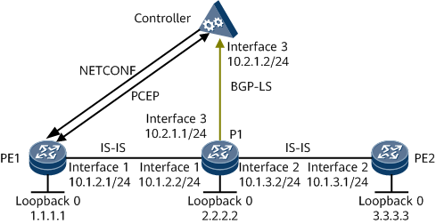
Networking Requirements
- IS-IS assigns labels to each neighbor and collects network topology information. P1 runs BGP-LS to collect topology information and reports the information to the controller.
- The controller uses the information to calculate a path and runs PCEP to deliver path information to ingress PE1.
- The controller sends the tunnel configuration information to the ingress node PE1 through NETCONF.
- The ingress node PE1 uses the delivered tunnel configurations and label stacks to establish an SR-MPLS TE tunnel. PE1 delegates the tunnel to the controller through PCE.

Configuration Roadmap
The configuration roadmap is as follows:
Assign an IP address and its mask to every interface and configure a loopback interface address as an MPLS LSR-ID on every node.
Configure LSR IDs and enable MPLS TE globally and on interfaces on each LSR.
Enable SR globally on each node.
Configure a label allocation mode and a topology information collection mode. In this example, the forwarders assign labels.
Configure the PCC and SR on each forwarder.
Configure the PCE server on the controller.
Procedure
- Assign an IP address and a mask to each interface.
# Configure PE1.
<HUAWEI> system-view
[~HUAWEI] sysname PE1
[*HUAWEI] commit
[~PE1] interface loopback 0
[*PE1-LoopBack0] ip address 1.1.1.1 32
[*PE1-LoopBack0] quit
[*PE1] interface gigabitethernet0/1/0
[*PE1-GigabitEthernet0/1/0] ip address 10.1.2.1 24
[*PE1-GigabitEthernet0/1/0] quit
[*PE1] commit
# Configure P1.
<HUAWEI> system-view
[~HUAWEI] sysname P1
[*HUAWEI] commit
[~P1] interface loopback 0
[*P1-LoopBack0] ip address 2.2.2.2 32
[*P1-LoopBack0] quit
[*P1] interface gigabitethernet0/1/0
[*P1-GigabitEthernet0/1/0] ip address 10.1.2.2 24
[*P1-GigabitEthernet0/1/0] quit
[*P1] interface gigabitethernet0/1/8
[*P1-GigabitEthernet0/1/8] ip address 10.1.3.2 24
[*P1-GigabitEthernet0/1/8] quit
[*P1] interface gigabitethernet0/1/16
[*P1-GigabitEthernet0/1/16] ip address 10.2.1.1 24
[*P1-GigabitEthernet0/1/16] quit
[*P1] commit
# Configure PE2.
<HUAWEI> system-view
[~HUAWEI] sysname PE2
[*HUAWEI] commit
[~PE2] interface loopback 0
[*PE2-LoopBack0] ip address 3.3.3.3 32
[*PE2-LoopBack0] quit
[*PE2] interface gigabitethernet0/1/8
[*PE2-GigabitEthernet0/1/8] ip address 10.1.3.1 24
[*PE2-GigabitEthernet0/1/8] quit
[*PE2] commit
- Configure IS-IS to advertise the route to each network segment to which each interface is connected and to advertise the host route to each loopback address that is used as an LSR ID.
# Configure PE1.
[~PE1] isis 1
[*PE1-isis-1] is-level level-2
[*PE1-isis-1] network-entity 10.0000.0000.0002.00
[*PE1-isis-1] quit
[*PE1] interface loopback 0
[*PE1-LoopBack0] isis enable 1
[*PE1-LoopBack0] quit
[*PE1] interface gigabitethernet0/1/0
[*PE1-GigabitEthernet0/1/0] isis enable 1
[*PE1-GigabitEthernet0/1/0] quit
[*PE1] commit
# Configure P1.
[~P1] isis 1
[*P1-isis-1] is-level level-2
[*P1-isis-1] network-entity 10.0000.0000.0003.00
[*P1-isis-1] quit
[*P1] interface loopback 0
[*P1-LoopBack0] isis enable 1
[*P1-LoopBack0] quit
[*P1] interface gigabitethernet0/1/0
[*P1-GigabitEthernet0/1/0] isis enable 1
[*P1-GigabitEthernet0/1/0] quit
[*P1] interface gigabitethernet0/1/8
[*P1-GigabitEthernet0/1/8] isis enable 1
[*P1-GigabitEthernet0/1/8] quit
[*P1] interface gigabitethernet0/1/16
[*P1-GigabitEthernet0/1/16] isis enable 1
[*P1-GigabitEthernet0/1/16] quit
[*P1] commit
# Configure PE2.
[~PE2] isis 1
[*PE2-isis-1] is-level level-2
[*PE2-isis-1] network-entity 10.0000.0000.0004.00
[*PE2-isis-1] quit
[*PE2] interface loopback 0
[*PE2-LoopBack0] isis enable 1
[*PE2-LoopBack0] quit
[*PE2] interface gigabitethernet0/1/8
[*PE2-GigabitEthernet0/1/8] isis enable 1
[*PE2-GigabitEthernet0/1/8] quit
[*PE2] commit
- Configure PCE on the forwarders and controller. For configuration details, see Configuration Files in this section.
- Configure basic MPLS functions and enable MPLS TE.
# Configure PE1.
[~PE1] mpls lsr-id 1.1.1.1
[*PE1] mpls
[*PE1-mpls] mpls te
[*PE1-mpls] quit
[*PE1] interface gigabitethernet 0/1/0
[*PE1-GigabitEthernet0/1/0] mpls
[*PE1-GigabitEthernet0/1/0] mpls te
[*PE1-GigabitEthernet0/1/0] commit
[~PE1-GigabitEthernet0/1/0] quit
The configurations on P1 and PE2 are the same as the configuration on PE1. The configuration details are not provided.
- Enable SR globally on each node.
# Configure PE1.
[~PE1] segment-routing
[*PE1-segment-routing] quit
[*PE1] commit
The configurations on P1 and PE2 are the same as the configuration on PE1. The configuration details are not provided.
- Configure a label allocation mode and a topology information collection mode. In this example, the forwarders assign labels.
Enable IS-IS SR-MPLS TE.
[~PE1] isis 1
[~PE1-isis-1] cost-style wide
[*PE1-isis-1] traffic-eng level-2
[*PE1-isis-1] segment-routing mpls
[*PE1-isis-1] bgp-ls enable level-2
[*PE1-isis-1] commit
[~PE1-isis-1] quit
The configurations on P1 and PE2 are the same as the configuration on PE1. The configuration details are not provided.
Configure the BGP-LS route advertisement capability on P1.
# Enable BGP-LS on P1 and establish a BGP-LS peer relationship with the controller.
[~P1] bgp 100
[*P1-bgp] peer 10.2.1.2 as-number 100
[*P1-bgp] link-state-family unicast
[*P1-bgp-af-ls] peer 10.2.1.2 enable
[*P1-bgp-af-ls] commit
[~P1-bgp-af-ls] quit
[~P1-bgp] quit
# Enable BGP-LS on the controller and establish a BGP-LS peer relationship with P1.
[~Controller] bgp 100
[*Controller-bgp] peer 10.2.1.1 as-number 100
[*Controller-bgp] link-state-family unicast
[*Controller-bgp-af-ls] peer 10.2.1.1 enable
[*Controller-bgp-af-ls] commit
[~Controller-bgp-af-ls] quit
[~Controller-bgp] quit
- The controller sends the tunnel configuration information to PE1 through NETCONF.
The detailed tunnel configuration delivered by the controller through NETCONF is as follows:
[~PE1] interface tunnel1
[*PE1-Tunnel1] ip address unnumbered interface loopback 0
[*PE1-Tunnel1] tunnel-protocol mpls te
[*PE1-Tunnel1] destination 3.3.3.3
[*PE1-Tunnel1] mpls te tunnel-id 1
[*PE1-Tunnel1] mpls te signal-protocol segment-routing
[*PE1-Tunnel1] mpls te pce delegate
[*PE1-Tunnel1] quit
[*PE1] commit
- Verify the configuration.
Run the display mpls te tunnel command on PE1 to view SR-MPLS TE tunnel information.
[~PE1] display mpls te tunnel
* means the LSP is detour LSP
-------------------------------------------------------------------------------
Ingress LsrId   Destination     LSPID In/OutLabel     R Tunnel-name
-------------------------------------------------------------------------------
1.1.1.1         3.3.3.3         21    -/330000        I Tunnel1
-------------------------------------------------------------------------------
R: Role, I: Ingress, T: Transit, E: Egress
Run the display mpls te tunnel path command on PE1 to view path information on the SR-MPLS TE tunnel.
[~PE1] display mpls te tunnel path
 Tunnel Interface Name : Tunnel1
 Lsp ID : 1.1.1.1 :1 :21
 Hop Information
  Hop 0 Label 330002 NAI 10.1.2.2
  Hop 1 Label 330002 NAI 10.1.3.1
Configuration Files
PE1 configuration file
#
sysname PE1
#
mpls lsr-id 1.1.1.1
#
mpls
 mpls te
#
pce-client
 capability segment-routing
 connect-server 10.2.1.2
#
segment-routing
#
isis 1
 is-level level-2
 cost-style wide
 bgp-ls enable level-2
 network-entity 10.0000.0000.0002.00
 traffic-eng level-2
 segment-routing mpls
#
interface GigabitEthernet0/1/0
 undo shutdown
 ip address 10.1.2.1 255.255.255.0
 isis enable 1
 mpls
 mpls te
#
interface LoopBack0
 ip address 1.1.1.1 255.255.255.255
 isis enable 1
#
 interface Tunnel1
 ip address unnumbered interface LoopBack0
 tunnel-protocol mpls te
 destination 3.3.3.3
 mpls te signal-protocol segment-routing
 mpls te tunnel-id 1
 mpls te pce delegate
#
return
P1 configuration file
#
sysname P1
#
mpls lsr-id 2.2.2.2
#
mpls
 mpls te
#
segment-routing
#
isis 1
 is-level level-2
 cost-style wide
 bgp-ls enable level-2
 network-entity 10.0000.0000.0003.00
 traffic-eng level-2
 segment-routing mpls
#
interface GigabitEthernet0/1/0
 undo shutdown
 ip address 10.1.2.2 255.255.255.0
 isis enable 1
 mpls
 mpls te
#
interface GigabitEthernet0/1/8
 undo shutdown
 ip address 10.1.3.2 255.255.255.0
 isis enable 1
 mpls
 mpls te
#
interface GigabitEthernet0/1/16
 undo shutdown
 ip address 10.2.1.1 255.255.255.0
#
interface LoopBack0
 ip address 2.2.2.2 255.255.255.255
 isis enable 1
#
bgp 100
 peer 10.2.1.2 as-number 100
 #
 ipv4-family unicast
  undo synchronization
  peer 10.2.1.2 enable
 #
 link-state-family unicast
  peer 10.2.1.2 enable
#
return
PE2 configuration file
#
sysname PE2
#
mpls lsr-id 3.3.3.3
#
mpls
 mpls te
#
segment-routing
#
isis 1
 is-level level-2
 cost-style wide
 bgp-ls enable level-2
 network-entity 10.0000.0000.0004.00
 traffic-eng level-2
 segment-routing mpls
#
interface GigabitEthernet0/1/8
 undo shutdown
 ip address 10.1.3.1 255.255.255.0
 isis enable 1
 mpls
 mpls te
#
interface LoopBack0
 ip address 3.3.3.3 255.255.255.255
 isis enable 1
#
return
Controller configuration file
#
sysname Controller
#
pce-server
 source-address 10.2.1.2
#
interface GigabitEthernet0/1/16
 undo shutdown
 ip address 10.2.1.2 255.255.255.0
#
bgp 100
 peer 10.2.1.1 as-number 100
 #
 ipv4-family unicast
  undo synchronization
  peer 10.2.1.1 enable
 #
 link-state-family unicast
  peer 10.2.1.1 enable
#
return