Example for Configuring Static BFD for IS-IS
This section describes how to configure static BFD for IS-IS, including configuring BFD parameters and enabling static BFD.
Networking Requirements
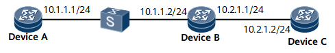
In Figure 1:
Device A and Device B are connected through a Layer 2 switch.
IS-IS runs on Device A, Device B, and Device C.
BFD is configured to detect the IS-IS neighbor relationship between Device A and Device B. If the link between Device A and Device B fails, BFD can fast detect the fault and notify it to IS-IS.
Device Name |
Interface |
IP Address |
|---|---|---|
Device A |
GE0/1/0 |
10.1.1.1/24 |
Device B |
GE0/1/0 |
10.1.1.2/24 |
GE0/1/8 |
10.2.1.1/24 |
|
Device C |
GE0/1/0 |
10.2.1.2/24 |

BFD for IS-IS cannot be used to detect the multi-hop link between Device A and Device C because the IS-IS neighbor relationship is not established between Device A and Device C.
Configuration Roadmap
The configuration roadmap is as follows:
Configure basic IS-IS functions on each router.
Enable BFD on Device A and Device B.
Data Preparation
To complete the configuration, you need the following data:
IS-IS process ID
Area addresses of Device A, Device B, and Device C
Levels of Device A, Device B, and Device C
Name of the BFD session established between Device A and Device B and peer IP address to be detected by BFD
Local and remote discriminators of the BFD session established between Device A and Device B
Procedure
- Configure an IP address for the interface on each router. For configuration details, see Configuration Files in this section.
- Configure basic IS-IS functions.
# Configure Device A.
[~DeviceA] isis 1
[*DeviceA-isis-1] is-level level-2
[*DeviceA-isis-1] network-entity aa.1111.1111.1111.00
[*DeviceA-isis-1] quit
[*DeviceA] interface gigabitethernet 0/1/0
[*DeviceA-GigabitEthernet0/1/0] isis enable 1
[*DeviceA-GigabitEthernet0/1/0] commit
[~DeviceA-GigabitEthernet0/1/0] quit
# Configure Device B.
[~DeviceB] isis 1
[*DeviceB-isis-1] is-level level-2
[*DeviceB-isis-1] network-entity aa.2222.2222.2222.00
[*DeviceB-isis-1] quit
[*DeviceB] interface gigabitethernet 0/1/0
[*DeviceB-GigabitEthernet0/1/0] isis enable 1
[*DeviceB-GigabitEthernet0/1/0] quit
[*DeviceB] interface gigabitethernet 0/1/8
[*DeviceB-GigabitEthernet0/1/8] isis enable 1
[*DeviceB-GigabitEthernet0/1/8] commit
[~DeviceB-GigabitEthernet0/1/8] quit
# Configure Device C.
[~DeviceC] isis 1
[*DeviceC-isis-1] is-level level-2
[*DeviceC-isis-1] network-entity aa.3333.3333.3333.00
[*DeviceC-isis-1] quit
[*DeviceC] interface gigabitethernet 0/1/0
[*DeviceC-GigabitEthernet0/1/0] isis enable 1
[*DeviceC-GigabitEthernet0/1/0] commit
[~DeviceC-GigabitEthernet0/1/0] quit
# After the preceding configurations. The command shows that the neighbor relationship has been established between Device A and Device B.
[~DeviceA] display isis peer
                          Peer information for ISIS(1)

System Id        Interface        Circuit Id          State HoldTime Type      PRI
---------------------------------------------------------------------------------
2222.2222.2222 GE0/1/0           2222.2222.2222.00    Up    23s      L2       64
Total Peer(s): 1
The IS-IS routing table of Device A has the routes to Device B and Device C.
[~DeviceA] display isis route
                         Route information for ISIS(1)
                         -----------------------------
                        ISIS(1) Level-2 Forwarding Table
                        --------------------------------
 IPV4 Destination    IntCost   ExtCost ExitInterface   NextHop        Flags
-------------------------------------------------------------------------
 10.1.1.0/24         10        NULL    GE0/1/0         Direct         D/-/L/-
 10.2.1.0/24         20        NULL    GE0/1/0         10.1.1.2      A/-/-/-
      Flags: D-Direct, A-Added to URT, L-Advertised in LSPs, S-IGP Shortcut,
                                 U-Up/Down Bit Set
      Protect Type: L-Link Protect, N-Node Protect
- Configure BFD.
# Enable BFD and configure a BFD session on Device A.
[~DeviceA] bfd
[*DeviceA-bfd] quit
[*DeviceA] bfd atob bind peer-ip 10.1.1.2 interface gigabitethernet0/1/0
[*DeviceA-bfd-session-atob] discriminator local 1
[*DeviceA-bfd-session-atob] discriminator remote 2
[*DeviceA-bfd-session-atob] commit
[~DeviceA-bfd-session-atob] quit
# Enable BFD and configure a BFD session on Device B.
[~DeviceB] bfd
[*DeviceB-bfd] quit
[*DeviceB] bfd btoa bind peer-ip 10.1.1.1 interface gigabitethernet0/1/0
[*DeviceB-bfd-session-btoa] discriminator local 2
[*DeviceB-bfd-session-btoa] discriminator remote 1
[*DeviceB-bfd-session-btoa] commit
[~DeviceB-bfd-session-btoa] quit
# After the preceding configurations, run the display bfd session command on Device A or Device B. The command shows that the BFD session has been Up.
Use the command output on Device A as an example.
[~DeviceA] display bfd session all
(w): State in WTR
(*): State is invalid
------------------------------------------------------------------------
Local   Remote   PeerIpAddr    State      Type       Interface Name
------------------------------------------------------------------------
1       2        10.1.1.2      Up         S_IP_IF    GigabitEthernet0/1/0
------------------------------------------------------------------------
     Total UP/DOWN Session Number : 1/0
- Enable static BFD on the IS-IS interface.
# Configure Device A.
[~DeviceA] interface gigabitethernet 0/1/0
[~DeviceA-GigabitEthernet0/1/0] isis bfd static
[*DeviceA-GigabitEthernet0/1/0] commit
[~DeviceA-GigabitEthernet0/1/0] quit
[~DeviceA] quit
# Configure Device B.
[~DeviceB] interface gigabitethernet 0/1/0
[~DeviceB-GigabitEthernet0/1/0] isis bfd static
[*DeviceB-GigabitEthernet0/1/0] commit
- Verify the configuration.
# Enable debugging on Device A.
<DeviceA> debugging isis adjacency
<DeviceA> debugging isis circuit-information
<DeviceA> terminal debugging
# Run the shutdown command on Gigabit Ethernet 0/1/0 of Device B to simulate a link fault.
[~DeviceB-GigabitEthernet0/1/0] shutdown
[*DeviceB-GigabitEthernet0/1/0] commit
# Display the logs on Device A. The command output shows that IS-IS has deleted the neighbor relationship between Device A and Device B after BFD notifies the fault.
#80/active/IsisAdjacencyChange/Major/occurredTime:2011-03-09 04:17:07/-/-/alarmI
D:0x08960007/VS=0:ISIS adjacency state change. (SysInstance=1, SysLevel=1, CircI
ndex=2, CircIfIndex=20, LspId=2222.2222.2222.00.00, AdjState=1, IfIndex=20, IfNa
me=GE0/1/0, Reason=BFD detected that the neighbor went Down, SubReason=14)
Configuration Files
Device A configuration file
#
sysname DeviceA
#
bfd
#
isis 1
 is-level level-2
 network-entity aa.1111.1111.1111.00
#
interface GigabitEthernet0/1/0
 undo shutdown
 ip address 10.1.1.1 255.255.255.0
 isis enable 1
 isis bfd static
#
bfd atob bind peer-ip 10.1.1.2 interface GigabitEthernet0/1/0
 discriminator local 1
 discriminator remote 2
#
return
Device B configuration file
#
sysname DeviceB
#
bfd
#
isis 1
 is-level level-2
 network-entity aa.2222.2222.2222.00
#
interface GigabitEthernet0/1/0
 undo shutdown
 ip address 10.1.1.2 255.255.255.0
 isis enable 1
 isis bfd static
#
interface GigabitEthernet0/1/8
 undo shutdown
 ip address 10.2.1.1 255.255.255.0
 isis enable 1
#
bfd btoa bind peer-ip 10.1.1.1 interface GigabitEthernet0/1/0
 discriminator local 2
 discriminator remote 1
#
return
Device C configuration file
#
sysname DeviceC
#
isis 1
 is-level level-2
 network-entity aa.3333.3333.3333.00
#
interface GigabitEthernet0/1/0
 undo shutdown
 ip address 10.2.1.2 255.255.255.0
 isis enable 1
#
return