Example for Configuring Dynamic BFD for IS-IS
This section describes how to configure dynamic BFD for IS-IS, including configuring basic IS-IS functions, setting the interface cost, configuring BFD for the IS-IS process, and configuring BFD for the IS-IS interface on each device.
Networking Requirements
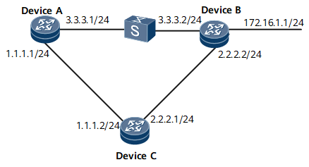
As shown in Figure 1:
IS-IS runs on Device A, Device B, and Device C.
BFD is enabled for the IS-IS processes on Device A, Device B, and Device C.
Service traffic is transmitted along the primary link Device A -> Device B. The link Device A -> Device C -> Device B functions as the backup link.
BFD is configured for the interfaces on the link between Device A and Device B. If the link fails, BFD can fast detect the fault and notify IS-IS of the fault so that service traffic can be transmitted through the backup link.
Device Name |
Interface |
IP Address |
|---|---|---|
Device A |
GE0/1/0 |
1.1.1.1/24 |
GE0/1/8 |
3.3.3.1/24 |
|
Device B |
GE0/1/0 |
2.2.2.2/24 |
GE0/1/8 |
3.3.3.2/24 |
|
GE0/1/16 |
172.16.1.1/24 |
|
Device C |
GE0/1/0 |
1.1.1.2/24 |
GE0/1/8 |
2.2.2.1/24 |
Configuration Roadmap
The configuration roadmap is as follows:
Configure basic IS-IS functions on each router for IP interworking.
Set the IS-IS interface cost to control route selection.
Enable global BFD.
Enable BFD for the IS-IS process on Device A, Device B, and Device C.
Enable BFD for the interfaces on Device A and Device B.
Data Preparation
To complete the configuration, you need the following data:
IS-IS process ID
Area addresses of Device A, Device B, and Device C
Interface costs of Device A and Device B
Numbers and types of the interfaces to be enabled with BFD on Device A, Device B, and Device C
Minimum interval at which BFD packets are received and sent and local detection multiplier on Device A and Device B
Procedure
- Configure an IP address for the interface on each router. For configuration details, see Configuration Files in this section.
- Configure basic IS-IS functions.
# Configure Device A.
[~DeviceA] isis
[*DeviceA-isis-1] is-level level-2
[*DeviceA-isis-1] network-entity 10.0000.0000.0001.00
[*DeviceA-isis-1] quit
[*DeviceA] interface gigabitethernet 0/1/0
[*DeviceA-GigabitEthernet0/1/0] isis enable 1
[*DeviceA-GigabitEthernet0/1/0] quit
[*DeviceA] interface gigabitethernet 0/1/8
[*DeviceA-GigabitEthernet0/1/8] isis enable 1
[*DeviceA-GigabitEthernet0/1/8] commit
[~DeviceA-GigabitEthernet0/1/8] quit
# Configure Device B.
[~DeviceB] isis
[*DeviceB-isis-1] is-level level-2
[*DeviceB-isis-1] network-entity 10.0000.0000.0002.00
[*DeviceB-isis-1] quit
[*DeviceB] interface gigabitethernet 0/1/0
[*DeviceB-GigabitEthernet0/1/0] isis enable 1
[*DeviceB-GigabitEthernet0/1/0] quit
[*DeviceB] interface gigabitethernet 0/1/8
[*DeviceB-GigabitEthernet0/1/8] isis enable 1
[*DeviceB-GigabitEthernet0/1/8] quit
[*DeviceB] interface gigabitethernet 0/1/16
[*DeviceB-GigabitEthernet0/1/16] isis enable 1
[*DeviceB-GigabitEthernet0/1/16] commit
[~DeviceB-GigabitEthernet0/1/16] quit
# Configure Device C.
[~DeviceC] isis
[*DeviceC-isis-1] is-level level-2
[*DeviceC-isis-1] network-entity 10.0000.0000.0003.00
[*DeviceC-isis-1] quit
[*DeviceC] interface gigabitethernet 0/1/0
[*DeviceC-GigabitEthernet0/1/0] isis enable 1
[*DeviceC-GigabitEthernet0/1/0] quit
[*DeviceC] interface gigabitethernet 0/1/8
[*DeviceC-GigabitEthernet0/1/8] isis enable 1
[*DeviceC-GigabitEthernet0/1/8] commit
[~DeviceC-GigabitEthernet0/1/8] quit
# Run the display isis peer command. The command output shows that the neighbor relationships have been established between Device A and Device B, and between Device A and Device C. Use the command output on Device A as an example.
[~DeviceA] display isis peer
-------------------------------------------------------------------------------
0000.0000.0002  GE0/1/8            0000.0000.0002.01 Up   9s       L2       64
0000.0000.0003  GE0/1/0            0000.0000.0001.02 Up   21s      L2       64
Total Peer(s): 2
# Display the routing table on each router. The routers have learned routes from each other. Use the command output on Device A as an example.
[~DeviceA] display ip routing-table
Route Flags: R - relay, D - download to fib, T - to vpn-instance, B - black hole route
------------------------------------------------------------------------------
Routing Table: _public_
         Destinations : 8        Routes : 9
Destination/Mask      Proto   Pre  Cost     Flags NextHop         Interface
        1.1.1.0/24    Direct  0    0           D  1.1.1.1         GigabitEthernet0/1/0
        1.1.1.1/32    Direct  0    0           D  127.0.0.1       InLoopBack0
        2.2.2.0/24    ISIS    15   20          D  1.1.1.2         GigabitEthernet0/1/0
        3.3.3.0/24    Direct  0    0           D  3.3.3.1         GigabitEthernet0/1/8
        3.3.3.1/32    Direct  0    0           D  127.0.0.1       InLoopBack0
      127.0.0.0/8     Direct  0    0           D  127.0.0.1       InLoopBack0
      127.0.0.1/32    Direct  0    0           D  127.0.0.1       InLoopBack0
      172.16.1.0/24 ISIS   15   20          D  3.3.3.2        GigabitEthernet0/1/8
As shown in the routing table, the next hop address of the route to 172.16.1.0/24 is 3.3.3.2, and traffic is transmitted on the primary link Device A -> Device B.
- Set the interface cost.
# Configure Device A.
[~DeviceA] interface gigabitethernet 0/1/8
[~DeviceA-GigabitEthernet0/1/8] isis cost 5
[*DeviceA-GigabitEthernet0/1/8] commit
[~DeviceA-GigabitEthernet0/1/8] quit
# Configure Device B.
[~DeviceB] interface gigabitethernet 0/1/8
[~DeviceB-GigabitEthernet0/1/8] isis cost 5
[*DeviceB-GigabitEthernet0/1/8] commit
[~DeviceB-GigabitEthernet0/1/8] quit
- Configure BFD for the IS-IS process.
# Enable BFD for the IS-IS process on Device A.
[~DeviceA] bfd
[*DeviceA-bfd] quit
[*DeviceA] isis
[*DeviceA-isis-1] bfd all-interfaces enable
[*DeviceA-isis-1] commit
[~DeviceA-isis-1] quit
# Enable BFD for the IS-IS process on Device B.
[~DeviceB] bfd
[*DeviceB-bfd] quit
[*DeviceB] isis
[*DeviceB-isis-1] bfd all-interfaces enable
[*DeviceB-isis-1] commit
[~DeviceB-isis-1] quit
# Enable BFD for the IS-IS process on Device C.
[~DeviceC] bfd
[*DeviceC-bfd] quit
[*DeviceC] isis
[*DeviceC-isis-1] bfd all-interfaces enable
[*DeviceC-isis-1] commit
[~DeviceC-isis-1] quit
# Run the display isis bfd session all command on Device A, Device B, or Device C. The command output shows that the BFD session is Up.
Use the command output on Device A as an example.
[~DeviceA] display isis bfd session all
                      BFD session information for ISIS(1)
                      -----------------------------------
Peer System ID : 0000.0000.0002        Interface : GE0/1/8
TX : 10            BFD State : up      Peer IP Address : 3.3.3.2
RX : 10            LocDis : 16385      Local IP Address: 3.3.3.1
Multiplier : 3     RemDis : 16388      Type : L2
Diag : No diagnostic information

Peer System ID : 0000.0000.0003        Interface : GE0/1/0
TX : 10            BFD State : up      Peer IP Address : 1.1.1.2
RX : 10            LocDis : 16386      Local IP Address: 1.1.1.1
Multiplier : 3     RemDis : 16387      Type : L2
Diag : No diagnostic information

Total BFD session(s): 2
The preceding information shows that the BFD sessions between Device A and Device B and between Device A and Device C are Up.
- Configure BFD for IS-IS interfaces.
# On GE 0/1/8 of Device A, configure BFD and set the minimum interval at which BFD packets are received and sent to 100 ms and the local detection multiplier to 4.
[~DeviceA] interface gigabitEthernet 0/1/8
[~DeviceA-GigabitEthernet0/1/8] isis bfd enable
[*DeviceA-GigabitEthernet0/1/8] isis bfd min-tx-interval 100 min-rx-interval 100 detect-multiplier 4
[*DeviceA-GigabitEthernet0/1/8] commit
[~DeviceA-GigabitEthernet0/1/8] quit
# On GE 0/1/8 of Device B, configure BFD and set the minimum interval at which BFD packets are received and sent to 100 ms and the local detection multiplier to 4.
[~DeviceB] interface gigabitethernet 0/1/8
[~DeviceB-GigabitEthernet0/1/8] isis bfd enable
[*DeviceB-GigabitEthernet0/1/8] isis bfd min-tx-interval 100 min-rx-interval 100 detect-multiplier 4
[*DeviceB-GigabitEthernet0/1/8] commit
[~DeviceB-GigabitEthernet0/1/8] quit
# Run the display isis bfd session all command on Device A or Device B. The command outputs show that BFD parameters have already taken effect. Use the command output on Device B as an example.
[~DeviceB] display isis bfd session all
                      BFD session information for ISIS(1)
                      -----------------------------------
Peer System ID : 0000.0000.0001        Interface : GE0/1/8
TX : 100           BFD State : up      Peer IP Address : 3.3.3.1
RX : 100           LocDis : 16385      Local IP Address: 3.3.3.2
Multiplier : 4     RemDis : 16385      Type : L2
Diag : No diagnostic information

Peer System ID : 0000.0000.0003        Interface : GE0/1/0
TX : 10            BFD State : up      Peer IP Address : 2.2.2.1
RX : 10            LocDis : 16385      Local IP Address: 2.2.2.2
Multiplier : 4     RemDis : 16385      Type : L2
Diag : No diagnostic information

Total BFD session(s): 2
- # Run the shutdown command on Gigabit Ethernet 0/1/8 on Device B to simulate the fault on the primary link.
[~DeviceB] interface gigabitethernet 0/1/8
[~DeviceB-GigabitEthernet0/1/8] shutdown
[*DeviceB-GigabitEthernet0/1/8] commit
- Verify the configuration.
# Display the routing table of Device A.
[~DeviceA] display ip routing-table
Route Flags: R - relay, D - download to fib, T - to vpn-instance, B - black hole route
------------------------------------------------------------------------------
Routing Table : _public_
         Destinations : 9        Routes : 9

Destination/Mask    Proto  Pre  Cost        Flags NextHop         Interface

        1.1.1.0/24  Direct 0    0             D  1.1.1.1         GigabitEthernet0/1/0
        1.1.1.1/32  Direct 0    0             D  127.0.0.1       GigabitEthernet0/1/0
      1.1.1.255/32  Direct 0    0             D  127.0.0.1       GigabitEthernet0/1/0
        2.2.2.0/24  ISIS   15   20            D  1.1.1.2         GigabitEthernet0/1/0
      127.0.0.0/8   Direct 0    0             D  127.0.0.1       InLoopBack0
      127.0.0.1/32  Direct 0    0             D  127.0.0.1       InLoopBack0
127.255.255.255/32  Direct 0    0             D  127.0.0.1       InLoopBack0
     172.16.1.0/24  ISIS   15   30            D  1.1.1.2         GigabitEthernet0/1/0
255.255.255.255/32  Direct 0    0             D  127.0.0.1       InLoopBack0
As shown in the routing table, the backup link Device A -> Device C -> Device B takes effect, and the next hop address of the route to 172.16.1.0/24 becomes 1.1.1.2.
# Run the display isis bfd session all command on Device A. The command output shows that only the BFD session between Device A and Device C is Up.
[~DeviceA] display isis bfd session all
                      BFD session information for ISIS(1)
                      -----------------------------------
Peer System ID : 0000.0000.0003        Interface : GE0/1/0
TX : 10            BFD State : up      Peer IP Address : 1.1.1.2
RX : 10            LocDis : 16385      Local IP Address: 1.1.1.1
Multiplier : 3     RemDis : 16388      Type : L2
Diag : No diagnostic information

Total BFD session(s): 1
Configuration Files
Device A configuration file
#
sysname DeviceA
#
bfd
#
isis 1
 is-level level-2
 bfd all-interfaces enable
 network-entity 10.0000.0000.0001.00
#
interface GigabitEthernet0/1/0
 undo shutdown
 ip address 1.1.1.1 255.255.255.0
 isis enable 1
#
interface GigabitEthernet0/1/8
 undo shutdown
 ip address 3.3.3.1 255.255.255.0
 isis enable 1
 isis cost 5
 isis bfd enable
 isis bfd min-tx-interval 100 min-rx-interval 100 detect-multiplier 4
#
return
Device B configuration file
#
sysname DeviceB
#
bfd
#
isis 1
 is-level level-2
 bfd all-interfaces enable
 network-entity 10.0000.0000.0002.00
#
interface GigabitEthernet0/1/0
 undo shutdown
 ip address 2.2.2.2 255.255.255.0
 isis enable 1
#
interface GigabitEthernet0/1/8
undo shutdown
 ip address 3.3.3.2 255.255.255.0
 isis enable 1
 isis cost 5
 isis bfd enable
 isis bfd min-tx-interval 100 min-rx-interval 100 detect-multiplier 4
#
interface GigabitEthernet0/1/16
 undo shutdown
 ip address 172.16.1.1 255.255.255.0
 isis enable 1
#
return
Device C configuration file
#
sysname DeviceC
#
bfd
#
isis 1
 is-level level-2
 bfd all-interfaces enable
 network-entity 10.0000.0000.0003.00
#
interface GigabitEthernet0/1/0
 undo shutdown
 ip address 1.1.1.2 255.255.255.0
 isis enable 1
#
interface GigabitEthernet0/1/8
 undo shutdown
 ip address 2.2.2.1 255.255.255.0
 isis enable 1
#
return