Example for Configuring IS-IS MT
The following example shows how to implement network interconnection using IS-IS on a network with an IPv4/IPv6 topology.
Networking Requirements
If an IPv4/IPv6 topology is deployed on a network, various end-to-end services, such as voice and data services share the same physical links. As a result, IPv4 or IPv6 packets are discarded, affecting transmission quality. To address this issue, configure MT and create separate IPv4 and IPv6 routing tables.
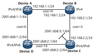
In Figure 1, Device A, Device C, and Device D support both IPv4 and IPv6, whereas Device B supports only IPv4.
Without IS-IS MT, IPv6 packets cannot reach Loopback 1 on Device C because the calculated SPT passes through Device B that does not support IPv6.
To ensure IPv6 packet transmission, enable IS-IS MT and create separate IPv4 and IPv6 routing tables.
Device Name |
Interface |
IP Address |
|---|---|---|
Device A |
GE 0/1/0 |
192.168.1.1/24 |
GE 0/1/8 |
2001:db8:1::1/64 |
|
Device B |
GE 0/1/0 |
192.168.1.2/24 |
GE 0/1/8 |
192.168.2.1/24 |
|
Device C |
Loopbak1 |
2001:db8:3::1/64 |
GE 0/1/0 |
2001:db8:2::2/64 |
|
GE 0/1/8 |
192.168.2.2/24 |
|
Device D |
GE 0/1/0 |
2001:db8:1::2/64 |
GE 0/1/8 |
2001:db8:2::1/64 |
Configuration Roadmap
The configuration roadmap is as follows:
Configure IPv4/IPv6 addresses for the interfaces on routers so that devices in different areas can communicate.
Enable IPv6 as well as global IPv4 and IPv6 topologies on the routers supporting the IPv4/IPv6 dual stack and enable a global IPv4 topology on Device B.
Configure basic IS-IS functions and link costs.
Create separate IPv4 and IPv6 topology instances on the routers supporting the IPv4/IPv6 dual stack and create an IPv4 topology instance on router B.
- Associate the interfaces with specified topology instances.
Data Preparation
To complete the configuration, you need the following data:
IP addresses of the interfaces on routers as shown in Figure 1, area ID (86), system ID of Device A (0000.0000.0001), system ID of Device B (0000.0000.0002), system ID of Device C (0000.0000.0003), system ID of Device D (0000.0000.0004), and level of all the routers (Level-1)
Cost of the link from Device D to Device A (6), cost of the link from Device A to Device B (4), cost of the link from Device B to Device C (3), cost of the link from Device D to Device C (14)
- IPv4 topology instance blue for all routers and IPv6 topology instance red for Device A, Device C, and Device D
Procedure
- Configure IP addresses for the interfaces.
Configure an IPv4 address and a mask for each interface on Device B, and configure IPv4 as well as IPv6 addresses and masks for each interface on Device A, Device C, and Device D based on Figure 1. For configuration details, see Configuration Files in this section.
- Enable IPv6 as well as global IPv4 and IPv6 topologies on the routers supporting the IPv4/IPv6 dual stack and enable a global IPv4 topology on Device B.
# Enable global IPv4 and IPv6 topologies on router A.
[~DeviceA] ip topology red
[*DeviceA] ipv6 topology blue
[*DeviceA] commit
The configurations on Device C and Device D are similar to that on router A. For configuration details, see Configuration Files in this section.
# Enable the global IPv4 topology on Device B.
[~DeviceB] ip topology red
[*DeviceB] commit
- Configure basic IS-IS functions and link costs.
For details about the configuration of basic IS-IS functions, see Examples for Configuring Basic IS-IS Functions.
# Set the cost of the link from Device A to Device B to 4.
[~DeviceA] interface gigabitethernet 0/1/0
[~DeviceA-GigabitEthernet0/1/0] isis cost 4
[*DeviceA-GigabitEthernet0/1/0] commit
[~DeviceA-GigabitEthernet0/1/0] quit
The configuration of other link costs is similar to that of the link from Device A to Device B.
- Create an IPv4 topology instance red for each router and an IPv6 topology instance blue for Device A, Device C, and Device D.
# Associate an IS-IS process with the IPv4 topology instance red and IPv6 topology instance blue on Device A.
[~DeviceA] isis
[~DeviceA-isis-1] ipv6 enable topology ipv6
[*DeviceA-isis-1] cost-style wide
[*DeviceA-isis-1] topology red topology-id 10
[*DeviceA-isis-1-topology-red] commit
[~DeviceA-isis-1-topology-red] quit
[*DeviceA-isis-1] ipv6 topology blue topology-id 20
[*DeviceA-isis-1-topology-blue] commit
[~DeviceA-isis-1-topology-blue] quit
[~DeviceA-isis-1] quit
The configurations on Device C and Device D are similar to that on Device A.
# Associate an IS-IS process with the IPv4 topology instance red on Device B.
[~DeviceB] isis
[~DeviceB-isis-1] cost-style wide
[*DeviceB-isis-1] topology red topology-id 10
[*DeviceB-isis-1-topology-red] commit
[~DeviceB-isis-1-topology-red] quit
[~DeviceB-isis-1] quit
- Associate the interfaces with specified topology instances.
# Use the interfaces on Device A as an example.
[~DeviceA] interface gigabitethernet 0/1/0
[~DeviceA-GigabitEthernet0/1/0] ip topology red enable
[*DeviceA-GigabitEthernet0/1/0] isis topology red
[*DeviceA-GigabitEthernet0/1/0] commit
[~DeviceA-GigabitEthernet0/1/0] quit
[~DeviceA] interface gigabitethernet 0/1/8
[~DeviceA-GigabitEthernet0/1/8] ip topology red enable
[*DeviceA-GigabitEthernet0/1/8] isis topology red
[*DeviceA-GigabitEthernet0/1/8] ipv6 topology blue enable
[*DeviceA-GigabitEthernet0/1/8] isis ipv6 topology blue
[*DeviceA-GigabitEthernet0/1/8] commit
[~DeviceA-GigabitEthernet0/1/8] quit
- Verify the configuration.
Run the display isis route command on the routers to view information about the learned routes. The command output on Device D is used as an example.
# Display the routing information on Device D.
[~DeviceD] display isis route
                         Route information for ISIS(1)
                         -----------------------------
                        ISIS(1) Level-1 Forwarding Table
                        --------------------------------
 IPV6 Dest.          ExitInterface   NextHop                    Cost       Flags
--------------------------------------------------------------------------
 2001:db8:3::/64    GE0/1/8       FE80::D11:0:36D4:1          14         A/-/-
 2001:db8:2::/64     GE0/1/8        Direct                      14         D/L/-
 2001:db8:1::/64     GE0/1/0        Direct                      6          D/L/-
     Flags: D-Direct, A-Added to URT, L-Advertised in LSPs, S-IGP Shortcut,
                               U-Up/Down Bit Set
     Protect Type: L-Link Protect, N-Node Protect
IPv6 routes are calculated only on the IPv6 topology. Therefore, the outbound interface of the route from Device D to 2001:db8:3::/64 is GE 0/1/8.
# Run the tracert command on Device D.
[~DeviceD] tracert ipv6 2001:db8:3::1
traceroute to 2001:db8:3::1  30 hops max,60 bytes packet
 1 2001:db8:3::1 62 ms  63 ms  31 ms
To make a comparison between the preceding routing information and the routing information when an IPv4/IPv6 topology is deployed, run the following commands.
[~DeviceD] isis 1
[~DeviceD-isis-1] ipv6 enable
[*DeviceD-isis-1] commit
Configuration modifications on Device A and Device C are similar to that on Device D.
After the configuration is modified, run the display isis route command on the routers once again to view information about the learned routes. The command output on Device D is used as an example.
# Display the routing information on Device D.
[~DeviceD] display isis route
                         Route information for ISIS(1)
                         -----------------------------
                        ISIS(1) Level-1 Forwarding Table
                        --------------------------------
 IPV6 Dest.         ExitInterface   NextHop                     Cost        Flags
--------------------------------------------------------------------------
 2001:db8:3::/64   GE0/1/0        FE80::200:5EFF:FE01:100     13          A/-/-
 2001:db8:2::/64    GE0/1/8         Direct                       14          D/L/-
 2001:db8:1::/64    GE0/1/0         Direct                       6           D/L/-
     Flags: D-Direct, A-Added to URT, L-Advertised in LSPs, S-IGP Shortcut,
                               U-Up/Down Bit Set
     Protect Type: L-Link Protect, N-Node Protect
The preceding output shows that the outbound interface of the route from Device D to 2001:db8:3::/64 is GE 0/1/0 because in the SPF calculation when an IPv4/IPv6 topology is deployed, the cost of the link passing through GE 0/1/0 to 2001:db8:3::1/64 is smaller.
[~DeviceD] tracert ipv6 2001:db8:3::1
 traceroute to 2001:db8:3::1  30 hops max,60 bytes packet
 1 2001:db8:1::1 31 ms  !N 31 ms  !N 32 ms  !N
However, the tracert command output shows that IPv6 packets cannot reach the destination.
# Display the routing information on Device A.
[~DeviceA] display isis route
                         Route information for ISIS(1)
                         -----------------------------
                        ISIS(1) Level-1 Forwarding Table
                        --------------------------------
 IPV4 Destination  IntCost  ExtCost ExitInterface  NextHop         Flags
------------------------------------------------------------------------
 192.168.2.0/24     7       NULL    GE0/1/0        192.168.1.2     A/-/-/-
 192.168.1.0/24     4       NULL    GE0/1/0        Direct          D/-/L/-
 IPV6 Dest.          ExitInterface   NextHop                      Cost       Flags
----------------------------------------------------------------------------
 2001:db8:2::/64     GE0/1/0         FE80::2E0:A9FF:FE47:8302     24         A/-/-
 2001:db8:1::/64     GE0/1/8         Direct                       10         D/L/-
     Flags: D-Direct, A-Added to URT, L-Advertised in LSPs, S-IGP Shortcut,
                               U-Up/Down Bit Set
     Protect Type: L-Link Protect, N-Node Protect
The preceding output shows that there is no outbound interface for the route from Device A to 2001:db8:3::/64 because the link between Device A and Device B does not support IPv6 and IPv6 packets from Device D are discarded.
Configuration Files
Device A configuration file
#
sysname DeviceA
#
 ip topology red
#
 ipv6 topology blue
#
isis 1
 cost-style wide
 network-entity 86.0000.0000.0001.00
 ipv6 enable topology ipv6
 #
 topology red topology-id 10
 #
 ipv6 topology blue topology-id 20
#
interface GigabitEthernet0/1/0
 undo shutdown
 ip address 192.168.1.1 255.255.255.0
 isis enable 1
 isis cost 4
 ip topology red enable
 isis topology red
#
interface GigabitEthernet0/1/8
 undo shutdown
 ipv6 enable
 ipv6 address 2001:db8:1::1/64
 isis ipv6 enable 1
 ipv6 topology blue enable
 isis ipv6 topology blue
#
return
Device B configuration file
#
 sysname DeviceB
#
 ip topology red
#
isis 1
 network-entity 86.0000.0000.0002.00
 #
 topology red topology-id 10
 #
#
interface GigabitEthernet0/1/0
 undo shutdown
 ip address 192.168.1.2 255.255.255.0
 isis enable 1
 ip topology red enable
 isis topology red
#
interface GigabitEthernet0/1/8
 undo shutdown
 ip address 192.168.2.1 255.255.255.0
 isis enable 1
 isis cost 3
 ip topology red enable
 isis topology red
#
return
Device C configuration file
#
sysname DeviceC
#
 ip topology red
#
 ipv6 topology blue
#
isis 1
 cost-style wide
 network-entity 86.0000.0000.0003.00
 ipv6 enable topology ipv6
 #
 topology red topology-id 10
 #
 ipv6 topology blue topology-id 20
#
interface GigabitEthernet0/1/0
 undo shutdown
 ipv6 enable
 ipv6 address 2001:db8:2::2/64
 isis ipv6 enable 1
 ip topology red enable
 isis topology red
 ipv6 topology blue enable
 isis ipv6 topology blue
#
interface GigabitEthernet0/1/8
 undo shutdown
 ip address 192.168.2.2 255.255.255.0
 isis enable 1
 ip topology red enable
 isis topology red
#
interface LoopBack1
 ipv6 enable
 ipv6 address 2001:db8:3::1/64
 isis ipv6 enable 1
#
return
Device D configuration file
#
sysname DeviceD
#
 ipv6 topology blue
#
isis 1
 is-level level-1
 cost-style wide
 network-entity 86.0000.0000.0004.00
 ipv6 enable topology ipv6
 #
 ipv6 topology blue topology-id 20
#
interface GigabitEthernet0/1/0
 undo shutdown
 ipv6 enable
 ipv6 address 2001:db8:1::2/64
 isis ipv6 enable 1
 isis cost 6
 isis ipv6 cost 6
 ipv6 topology blue enable
 isis ipv6 topology blue
#
interface GigabitEthernet0/1/8
 undo shutdown
 ipv6 enable
 ipv6 address 2001:db8:2::1/64
 isis ipv6 enable 1
 isis cost 14
 isis ipv6 cost 14
 ipv6 topology blue enable
 isis ipv6 topology blue
#
return