Example for Configuring the Access of PW Redundancy in Independent Mode to L3VPN (IP RAN Scenario)
Mixed VPN is a bearer mode used by the IPTime MBB solution. This solution is a major solution for IP mobile backhaul (MBH) networks that Huawei builds.
Networking Requirements
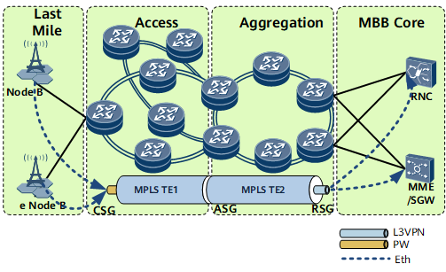
The mixed VPN solution provides excellent FMC capabilities and adopts a simple and flexible networking scheme. The network between CSGs and RSGs is designed hierarchically to meet large-scale service bearer requirements.
CSGs are connected to form the access network, and ASGs and RSGs are connected to form the aggregation network. All these devices can be flexibly deployed to meet 2G, 3G, and LTE service bearer requirements. See Figure 1.

This example uses Virtual-Ethernet interface to configure L2VPN accessing L3VPN. As a VE interface is bound to only one board, when the board is faulty, services are interrupted. To improve service reliability, create two global virtual interfaces: Global-VE1 and Global-VE2. Global-VE1 is configured as an L2VE interface to terminate L2VPN services, and the Global-VE2 is configured as an L3VE interface to access an L3VPN network. Other configurations remain unchanged
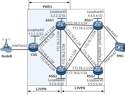
H-VPLS (PWE3 accessing VPLS) or PWE3 can be used to deploy the L2VPN. This example uses Ethernet base stations and PWE3+L3VPN for service bearer. Figure 2 shows a simplified single-ring network. The current versions are used for networking. The configurations on the CSGs and ASGs are mainly described here.
- In this example, interface1 and interface2 represent GE0/1/0 and GE0/1/3, respectively.
Device |
Interface |
Peer Device |
IP Address |
|---|---|---|---|
CSG |
GE0/1/1 |
ASG1 |
172.16.1.1/24 |
GE0/1/2 |
ASG2 |
172.16.4.1/24 |
|
GE0/1/3 |
NodeB |
- |
|
ASG1 |
GE0/1/0 |
ASG2 |
172.16.2.2/24 |
GE0/1/1 |
CSG |
172.16.1.2/24 |
|
GE0/1/3 |
RSG1 |
172.16.3.1/24 |
|
GE0/1/4 |
RSG2 |
172.16.8.1/24 |
|
ASG2 |
GE0/1/0 |
ASG1 |
172.16.2.1/24 |
GE0/1/2 |
CSG |
172.16.4.2/24 |
|
GE0/1/3 |
RSG2 |
172.16.6.1/24 |
|
GE0/1/4 |
RSG1 |
172.16.7.1/24 |
|
RSG1 |
GE0/1/0 |
RSG2 |
- |
GE0/1/1 |
ASG1 |
172.16.3.2/24 |
|
GE0/1/2 |
ASG2 |
172.16.7.2/24 |
|
GE0/1/3 |
RNC |
- |
|
RSG2 |
GE0/1/0 |
RSG1 |
- |
GE0/1/1 |
ASG2 |
172.16.6.2/24 |
|
GE0/1/2 |
ASG1 |
172.16.8.2/24 |
|
GE0/1/3 |
RNC |
- |
Configuration Roadmap
The configuration roadmap is as follows:
Configure IP addresses and routes.
Configure MPLS and public network tunnels. Specifically:
- Configure TE tunnels under protection between the CSG and each ASG.
- Configure LSPs between ASGs and RSGs.
Configure PW redundancy in independent mode:
- Configure MPLS LDP remote sessions between the CSG and ASGs.
- Configure service PWs.
- Configure an mPW.
- Configure BFD to detect the mPW.
- Configure primary/secondary status negotiation for PWs.
Configure an L3VPN.
- Configure VPN instances on ASGs and RSGs.
- Configure a VE group on each ASG, and bind the L3VE sub-interface in the group to the VPN instance on each ASG.
- Establish MP-IBGP peer relationships between ASGs and RSGs.
- Import direct routes to VPN instances on ASGs and RSGs.
- Configure VPN FRR.
Configure VRRP.
- Configure service VRRP and mVRRP on ASGs to determine a gateway for base stations.
- Configure service VRRP on RSGs to determine their master/backup status.
Data Preparation
To complete the configuration, you need the following data.
Interface numbers, interface IP addresses, and OSPF process IDs
LSR IDs
L2VCs' destination IP addresses, VC IDs, and VC types
Names, local discriminators, and remote discriminators of BFD sessions
VE group number
Numbers and priorities of VRRP groups
Procedure
- Configure interface IP addresses and a routing protocol.
- Configure a routing protocol on the CSG, ASG1, ASG2, RSG1, and RSG2 for them to be routable to each other. In this example, OSPF is used.
One access ring is used in this example. If multiple access rings are available, each access ring belongs to a different area. If IS-IS is used, each access ring belongs to a different IS-IS process, and a different NET is deployed for each access ring. If the planned network is small, the entire network can be planned as a Level-2 area.
After the configuration is complete, run the display ip routing-table command on the CSG, ASGs, and RSGs. These devices have learned routes from each other. Note that when configuring OSPF, you need to configure OSPF to advertise the 32-bit loopback interface addresses (LSR IDs) of the CSG, ASGs, and RSGs.
For configuration details, see Configuration Files in this section.
- Configure a routing protocol on the CSG, ASG1, ASG2, RSG1, and RSG2 for them to be routable to each other. In this example, OSPF is used.
- Configure basic MPLS functions and public network tunnels.
- Configure explicit path-based TE tunnels between the CSG and ASG1 and between the CSG and ASG2.
- Configure LSPs between ASG1 and ASG2 and between ASGs and RSGs.
- To improve reliability, enable the Resource Reservation Protocol (RSVP) GR, LDP GR, and OSPF GR.
For configuration details, see Configuration Files in this section.
- Configure PW redundancy.
- Configure MPLS LDP remote sessions between the CSG and ASGs.
In this configuration example, TE tunnels are configured between the CSG and ASGs, and MPLS LDP is not configured. PWE3, however, uses extended LDP signaling to distribute VPN labels. Therefore, MPLS LDP remote sessions need to be configured between the CSG and ASGs. An LDP LSP is configured to directly connect ASGs, and no LDP remote session needs to be configured between ASGs.
# Configure the CSG.
[~CSG] mpls ldp
[*CSG-mpls-ldp] quit
[*CSG] mpls ldp remote-peer 2.2.2.2
[*CSG-mpls-ldp-remote-2.2.2.2] remote-ip 2.2.2.2
[*CSG-mpls-ldp-remote-2.2.2.2] quit
[*CSG] mpls ldp remote-peer 3.3.3.3
[*CSG-mpls-ldp-remote-3.3.3.3] remote-ip 3.3.3.3
[*CSG-mpls-ldp-remote-3.3.3.3] quit
[*CSG] commit
# Configure ASG1.
[~ASG1] mpls ldp
[*ASG1-mpls-ldp] quit
[*ASG1] mpls ldp remote-peer 1.1.1.1
[*ASG1-mpls-ldp-remote-1.1.1.1] remote-ip 1.1.1.1
[*ASG1-mpls-ldp-remote-1.1.1.1] quit
[*ASG1] commit
# Configure ASG2.
[~ASG2] mpls ldp
[*ASG2-mpls-ldp] quit
[*ASG2] mpls ldp remote-peer 1.1.1.1
[*ASG2-mpls-ldp-remote-1.1.1.1] remote-ip 1.1.1.1
[*ASG2-mpls-ldp-remote-1.1.1.1] quit
[*ASG2] commit
# Verify the configuration. Run the display mpls ldp session all command on the CSG and ASGs to check whether the LDP session status is Operational. If the LDP session status is Operational, the LDP session has been established. Use the CSG as an example.
[~CSG] display mpls ldp session all
 LDP Session(s) in Public Network
 Codes: LAM(Label Advertisement Mode), SsnAge Unit(DDDD:HH:MM)
 An asterisk (*) before a session means the session is being deleted.
 ------------------------------------------------------------------------------
 PeerID             Status      LAM  SsnRole  SsnAge      KASent/Rcv
 ------------------------------------------------------------------------------
 2.2.2.2:0          Operational DU   Passive  0000:00:47  190/190
 3.3.3.3:0          Operational DU   Passive  0000:00:47  190/190
 ------------------------------------------------------------------------------
 TOTAL: 2 session(s) Found.
- Configure primary/secondary status negotiation for PWs.
If PW redundancy in independent mode is used, mVRRP needs to be configured on ASGs to determine the master/backup status of ASGs, so that after PWs are associated with mVRRP, the primary/secondary status of PWs can be determined.
# Configure ASG1.
[~ASG1] interface gigabitethernet  0/1/0
[*ASG1-GigabitEthernet0/1/0] vrrp vrid 20 virtual-ip 172.16.2.3
[*ASG1-GigabitEthernet0/1/0] admin-vrrp vrid 20 ignore-if-down
[*ASG1-GigabitEthernet0/1/0] vrrp vrid 20 priority 150
[*ASG1-GigabitEthernet0/1/0] quit
[*ASG1] interface virtual-ethernet 0/1/0.1
[*ASG1-Virtual-Ethernet0/1/0.1] mpls l2vc track admin-vrrp interface gigabitethernet  0/1/0 vrid 20 pw-redundancy
[*ASG1-Virtual-Ethernet0/1/0.1] quit
[*ASG1] commit
# Configure ASG2.
[~ASG2] interface gigabitethernet 0/1/0
[*ASG2-GigabitEthernet0/1/0] vrrp vrid 20 virtual-ip 172.16.2.3
[*ASG2-GigabitEthernet0/1/0] admin-vrrp vrid 20 ignore-if-down
[*ASG2-GigabitEthernet0/1/0] quit
[*ASG2] interface virtual-ethernet 0/1/0.1
[*ASG2-Virtual-Ethernet0/1/0.1] mpls l2vc track admin-vrrp interface gigabitethernet 0/1/0 vrid 20 pw-redundancy
[*ASG2-Virtual-Ethernet0/1/0.1] quit
[*ASG2] commit
# Verify the configuration. Run the display vrrp command on ASG1 and ASG2 to check the master/backup status of each ASG. The command output on ASG1 is used as an example. Because the default VRRP priority is 100, ASG1 whose VRRP priority is 150 assumes the master role.
[~ASG1] display vrrp
  GigabitEthernet0/1/0 | Virtual Router 1
    State            : Master
    Virtual IP       : 172.16.2.3
    Master IP        : 172.16.2.2
    Local IP         : 172.16.2.2
    PriorityRun      : 150
    PriorityConfig   : 150
    MasterPriority   : 150
    Preempt          : YES   Delay Time : 0
    Hold Multiplier  : 3
    TimerRun         : 1
    TimerConfig      : 1
    Auth Type        : NONE
    Virtual Mac      :  00e0-fc12-3456
    Check TTL        : YES
    Config type      : admin-vrrp
    Create time      : 2010-09-05 15:25:47
    Last change time : 2010-09-05 15:25:51
- Configure MPLS LDP remote sessions between the CSG and ASGs.
- Configure an L3VPN.
- Configure VRRP on ASG1 and ASG2 to determine a gateway for base stations.
For configuration details, see Configuration Files in this section and "VRRP Configuration" located under NetEngine 8000 F Configuration Guide > Network Reliability.
- Configure VRRP to determine the master/backup status of RSGs.
For configuration details, see Configuration Files in this section and "VRRP Configuration" located under NetEngine 8000 F Configuration Guide > Network Reliability.
Configuration Files
CSG configuration file
#
 sysname CSG
#
 mpls lsr-id 1.1.1.1
 mpls
  mpls te
  mpls rsvp-te
  mpls rsvp-te hello
  mpls te cspf
#
 mpls l2vpn
#
 explicit-path to_sr1
  next hop 172.16.1.2
  next hop 2.2.2.2
#
 explicit-path to_sr2
  next hop 172.16.4.2
  next hop 3.3.3.3
#
mpls ldp
 graceful-restart
#
 mpls ldp remote-peer 2.2.2.2
 remote-ip 2.2.2.2
#
 mpls ldp remote-peer 3.3.3.3
 remote-ip 3.3.3.3
#
interface GigabitEthernet0/1/1
 undo shutdown
 ip address 172.16.1.1 255.255.255.0
 mpls
 mpls te
 mpls rsvp-te
 mpls rsvp-te hello
#
interface GigabitEthernet0/1/2
 undo shutdown
 ip address 172.16.4.1 255.255.255.0
 mpls
 mpls te
 mpls rsvp-te
 mpls rsvp-te hello
#
interface GigabitEthernet0/1/3
 undo shutdown
#
interface GigabitEthernet0/1/3.10
 vlan-type dot1q 10
 mpls l2vc 2.2.2.2 100 tunnel-policy policy1 control-word
 mpls l2vc 3.3.3.3 200 tunnel-policy policy1 secondary control-word
 mpls l2vpn redundancy independent
 mpls l2vpn stream-dual-receiving
#
interface LoopBack0
 ip address 1.1.1.1 255.255.255.255
#
interface Tunnel11
 ip address unnumbered interface LoopBack0
 tunnel-protocol mpls te
 destination 2.2.2.2
 mpls te tunnel-id 100
 mpls te record-route
 mpls te signal-protocol rsvp-te
 mpls te path explicit-path to_sr1
 mpls te backup hot-standby wtr 15
 mpls te reserved-for-binding
#
interface Tunnel12
 ip address unnumbered interface LoopBack0
 tunnel-protocol mpls te
 destination 3.3.3.3
 mpls te tunnel-id 200
 mpls te record-route
 mpls te signal-protocol rsvp-te
 mpls te path explicit-path to_sr2
 mpls te backup hot-standby wtr 15
 mpls te reserved-for-binding
#
ospf 100
 opaque-capability enable
 graceful-restart
 area 0.0.0.0
  network 1.1.1.1 0.0.0.0
  network 172.16.1.0 0.0.0.255
  network 172.16.4.0 0.0.0.255
  mpls-te enable
#
tunnel-policy policy1
 tunnel binding destination 2.2.2.2 te Tunnel11
 tunnel binding destination 3.3.3.3 te Tunnel12
#
bfd master bind pw interface GigabitEthernet0/1/3.10 remote-peer 2.2.2.2 pw-ttl auto-calculate
 discriminator local 2
 discriminator remote 2
 commit
#
return
ASG1 configuration file
#
 sysname ASG1
#
ip vpn-instance vpna
 ipv4-family
  route-distinguisher 1:1
  apply-label per-instance
  vpn frr
  vpn-target 1:1 export-extcommunity
  vpn-target 1:1 import-extcommunity
#
 bfd
#
 mpls lsr-id 2.2.2.2
 mpls
  mpls te
  mpls rsvp-te
  mpls rsvp-te hello
  mpls te cspf
#
 mpls l2vpn
#
 explicit-path to_csg
  next hop 172.16.1.1
  next hop 1.1.1.1
#
mpls ldp
 graceful-restart
#
 mpls ldp remote-peer 1.1.1.1
 remote-ip 1.1.1.1
#
interface GigabitEthernet0/1/0
 undo shutdown
 ip address 172.16.2.2 255.255.255.0
 vrrp vrid 1 virtual-ip 172.16.2.3
 admin-vrrp vrid 1 ignore-if-down
 vrrp vrid 1 priority 150
 mpls
 mpls ldp
#
interface GigabitEthernet0/1/1
 undo shutdown
 ip address 172.16.1.2 255.255.255.0
 mpls
 mpls te
 mpls rsvp-te
 mpls rsvp-te hello
#
interface GigabitEthernet0/1/3
 undo shutdown
 ip address 172.16.3.1 255.255.255.0
 mpls
 mpls ldp
#
interface GigabitEthernet0/1/4
 undo shutdown
 ip address 172.16.8.1 255.255.255.0
 mpls
 mpls ldp
#
interface Virtual-Ethernet0/1/0
 ve-group 1 l2-terminate
#
interface Virtual-Ethernet0/1/0.1
 mpls l2vc 1.1.1.1 100 tunnel-policy policy1 ignore-standby-state
 mpls l2vc track admin-vrrp interface GigabitEthernet0/1/0 vrid 20 pw-redundancy
#
interface Virtual-Ethernet0/1/1
 ve-group 1 l3-access
#
interface Virtual-Ethernet0/1/1.1
 vlan-type dot1q 10
 ip binding vpn-instance vpna
 ip address 10.0.0.2 255.255.255.0
 direct-route track pw-state degrade-cost 30
 vrrp vrid 10 virtual-ip 10.0.0.3
 vrrp vrid 10 track admin-vrrp interface GigabitEthernet0/1/0 vrid 20
#
interface LoopBack0
 ip address 2.2.2.2 255.255.255.255
#
interface LoopBack1
 mpls l2vc 3.3.3.3 400 control-word admin
#
interface Tunnel11
 ip address unnumbered interface LoopBack0
 tunnel-protocol mpls te
 destination 1.1.1.1
 mpls te tunnel-id 100
 mpls te record-route
 mpls te signal-protocol rsvp-te
 mpls te path explicit-path to_csg
 mpls te backup hot-standby wtr 15
 mpls te reserved-for-binding
#
bgp 100
 graceful-restart
 peer 3.3.3.3 as-number 100
 peer 3.3.3.3 connect-interface LoopBack0
 peer 4.4.4.4 as-number 100
 peer 4.4.4.4 connect-interface LoopBack0
 peer 5.5.5.5 as-number 100
 peer 5.5.5.5 connect-interface LoopBack0
 #
 ipv4-family unicast
  undo synchronization
  peer 3.3.3.3 enable
  peer 4.4.4.4 enable
  peer 5.5.5.5 enable
 #
 ipv4-family vpnv4
  policy vpn-target
  peer 3.3.3.3 enable
  peer 4.4.4.4 enablef
  peer 5.5.5.5 enable
 #
 ipv4-family vpn-instance vpna
  import-route direct
#
ospf 100
 opaque-capability enable
 graceful-restart
 area 0.0.0.0
  network 2.2.2.2 0.0.0.0
  network 172.16.1.0 0.0.0.255
  network 172.16.3.0 0.0.0.255
  network 172.16.2.0 0.0.0.255
  network 172.16.8.0 0.0.0.255
  mpls-te enable
#
tunnel-policy policy1
 tunnel binding destination 1.1.1.1 te Tunnel11
#
bfd pw1 bind pw interface virtual-ethernet0/1/0.1
 discriminator local 2
 discriminator remote 2
 commit
#
return
ASG2 configuration file
#
 sysname ASG2
#
ip vpn-instance vpna
 ipv4-family
  route-distinguisher 1:1
  apply-label per-instance
  vpn frr
  vpn-target 1:1 export-extcommunity
  vpn-target 1:1 import-extcommunity
#
 bfd
#
 mpls lsr-id 3.3.3.3
 mpls
  mpls te
  mpls rsvp-te
  mpls rsvp-te hello
  mpls te cspf
#
 mpls l2vpn
#
 explicit-path to_csg
  next hop 172.16.4.1
  next hop 1.1.1.1
#
mpls ldp
 graceful-restart
#
 mpls ldp remote-peer 1.1.1.1
 remote-ip 1.1.1.1
#
interface GigabitEthernet0/1/0
 undo shutdown
 ip address 172.16.2.1 255.255.255.0
 vrrp vrid 20 virtual-ip 172.16.2.3
 admin-vrrp vrid 20 ignore-if-down
 mpls
 mpls ldp
#
interface GigabitEthernet0/1/1
 undo shutdown
#
interface GigabitEthernet0/1/2
 undo shutdown
 ip address 172.16.4.2 255.255.255.0
 mpls
 mpls te
 mpls rsvp-te
#
interface GigabitEthernet0/1/3
 undo shutdown
 ip address 172.16.6.1 255.255.255.0
 mpls
 mpls ldp
#
interface GigabitEthernet0/1/4
 undo shutdown
 ip address 172.16.7.1 255.255.255.0
 mpls
 mpls ldp
#
interface Virtual-Ethernet0/1/0
 ve-group 1 l2-terminate
#
interface Virtual-Ethernet0/1/0.1
 mpls
 mpls l2vc 1.1.1.1 200 tunnel-policy policy1 ignore-standby-state
 mpls l2vc track admin-vrrp interface GigabitEthernet0/1/0 vrid 20 pw-redundancy
#
interface Virtual-Ethernet0/1/1
 ve-group 1 l3-access
#
interface Virtual-Ethernet0/1/1.1
 vlan-type dot1q 10
 ip binding vpn-instance vpna
 ip address 10.0.0.4 255.255.255.0
 vrrp vrid 10 virtual-ip 10.0.0.3
 vrrp vrid 10 track admin-vrrp interface GigabitEthernet0/1/0 vrid 20
#
interface LoopBack0
 ip address 3.3.3.3 255.255.255.255
#
interface LoopBack1
 mpls l2vc 2.2.2.2 400 control-word admin
#
interface Tunnel12
 ip address unnumbered interface LoopBack0
 tunnel-protocol mpls te
 destination 1.1.1.1
 mpls te tunnel-id 200
 mpls te record-route
 mpls te signal-protocol rsvp-te
 mpls te path explicit-path to_csg
 mpls te backup hot-standby wtr 15
 mpls te reserved-for-binding
#
bgp 100
 graceful-restart
 peer 2.2.2.2 as-number 100
 peer 2.2.2.2 connect-interface LoopBack0
 peer 4.4.4.4 as-number 100
 peer 4.4.4.4 connect-interface LoopBack0
 peer 5.5.5.5 as-number 100
 peer 5.5.5.5 connect-interface LoopBack0
 #
 ipv4-family unicast
  undo synchronization
  peer 2.2.2.2 enable
  peer 4.4.4.4 enable
  peer 5.5.5.5 enable
 #
 ipv4-family vpnv4
  policy vpn-target
  peer 2.2.2.2 enable
  peer 4.4.4.4 enable
  peer 5.5.5.5 enable
 #
 ipv4-family vpn-instance vpna
  import-route direct
#
ospf 100
 opaque-capability enable
 graceful-restart
 area 0.0.0.0
  network 3.3.3.3 0.0.0.0
  network 172.16.2.0 0.0.0.255
  network 172.16.7.0 0.0.0.255
  network 172.16.4.0 0.0.0.255
  network 172.16.6.0 0.0.0.255
  mpls-te enable
#
tunnel-policy policy1
 tunnel binding destination 1.1.1.1 te Tunnel12
#
bfd pw2 bind pw interface virtual-ethernet0/1/0.1
 discriminator local 2
 discriminator remote 2
 commit
#
return
RSG1 configuration file
#
 sysname RSG1
#
 vlan batch 10
#
ip vpn-instance vpna
 ipv4-family
  route-distinguisher 1:1
  apply-label per-instance
  vpn frr
  vpn-target 1:1 export-extcommunity
  vpn-target 1:1 import-extcommunity
#
 mpls lsr-id 4.4.4.4
#
 mpls l2vpn
#
mpls ldp
 graceful-restart
#
interface Vlanif10
 ip binding vpn-instance vpna
 ip address 10.0.1.1 255.255.255.0
 vrrp vrid 1 virtual-ip 10.0.1.3
 vrrp vrid 1 priority 150
#
interface GigabitEthernet0/1/0
 portswitch
 undo shutdown
 port link-type trunk
 port trunk allow-pass vlan 10
#
interface GigabitEthernet0/1/1
 undo shutdown
 ip address 172.16.3.2 255.255.255.0
 mpls
 mpls ldp
#
interface GigabitEthernet0/1/2
 undo shutdown
 ip address 172.16.7.2 255.255.255.0
 mpls
 mpls ldp
#
interface GigabitEthernet0/1/3
 portswitch
 undo shutdown
 port link-type trunk
 port trunk allow-pass vlan 10
#
interface LoopBack0
 ip address 4.4.4.4 255.255.255.255
#
bgp 100
 graceful-restart
 peer 2.2.2.2 as-number 100
 peer 2.2.2.2 connect-interface LoopBack0
 peer 3.3.3.3 as-number 100
 peer 3.3.3.3 connect-interface LoopBack0
 peer 5.5.5.5 as-number 100
 peer 5.5.5.5 connect-interface LoopBack0
 #
 ipv4-family unicast
  undo synchronization
  peer 2.2.2.2 enable
  peer 3.3.3.3 enable
  peer 5.5.5.5 enable
 #
 ipv4-family vpnv4
  policy vpn-target
  peer 2.2.2.2 enable
  peer 3.3.3.3 enable
  peer 5.5.5.5 enable
 #
 ipv4-family vpn-instance vpna
  import-route direct
#
ospf 100
 opaque-capability enable
 graceful-restart
 area 0.0.0.0
  network 4.4.4.4 0.0.0.0
  network 172.16.3.0 0.0.0.255
  network 172.16.7.0 0.0.0.255
  mpls-te enable
#
return
RSG2 configuration file
#
 sysname RSG2
#
 vlan batch 10
#
ip vpn-instance vpna
 ipv4-family
  route-distinguisher 11
  apply-label per-instance
  vpn frr
  vpn-target 11 export-extcommunity
  vpn-target 11 import-extcommunity
#
 mpls lsr-id 5.5.5.5
#
 mpls l2vpn
#
mpls ldp
 graceful-restart
#
interface Vlanif10
 ip binding vpn-instance vpna
 ip address 10.0.1.2 255.255.255.0
 vrrp vrid 1 virtual-ip 10.0.1.3
#
interface GigabitEthernet0/1/0
 portswitch
 undo shutdown
 port link-type trunk
 port trunk allow-pass vlan 10
#
interface GigabitEthernet0/1/1
 undo shutdown
 ip address 172.16.6.2 255.255.255.0
 mpls
 mpls ldp
#
interface GigabitEthernet0/1/2
 undo shutdown
 ip address 172.16.8.2 255.255.255.0
 mpls
 mpls ldp
#
interface GigabitEthernet0/1/3
 portswitch
 undo shutdown
 port link-type trunk
 port trunk allow-pass vlan 10
#
interface LoopBack0
 ip address 5.5.5.5 255.255.255.255
#
bgp 100
 graceful-restart
 peer 2.2.2.2 as-number 100
 peer 2.2.2.2 connect-interface LoopBack0
 peer 3.3.3.3 as-number 100
 peer 3.3.3.3 connect-interface LoopBack0
 peer 4.4.4.4 as-number 100
 peer 4.4.4.4 connect-interface LoopBack0
 #
 ipv4-family unicast
  undo synchronization
  peer 2.2.2.2 enable
  peer 3.3.3.3 enable
  peer 4.4.4.4 enable
 #
 ipv4-family vpnv4
  policy vpn-target
  peer 2.2.2.2 enable
  peer 3.3.3.3 enable
  peer 4.4.4.4 enable
 #
 ipv4-family vpn-instance vpna
  import-route direct
#
ospf 100
 opaque-capability enable
 graceful-restart
 area 0.0.0.0
  network 5.5.5.5 0.0.0.0
  network 172.16.8.0 0.0.0.255
  network 172.16.6.0 0.0.0.255
  mpls-te enable
#
return