Configuring an L2VPN to Access Multiple L3VPNs Through Sub-interfaces for VLAN Tag Termination
This section describes how to configure an L2VPN to access L3VPNs through the L3VE sub-interface in QinQ or Dot1q termination mode. To be specific, you can configure the L3VE sub-interface to terminate user packets of different inner VLAN tags, and then these packets can be sent to different L3VPNs.
Applicable Environment
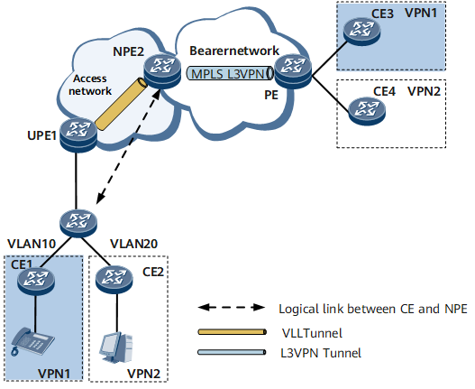
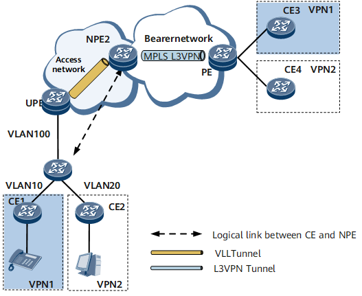
As shown in Figure 1 and Figure 2, different services, such as data, voice, and video, are running on a user network. By adding different VLAN tags to different service packets, sub-interfaces for Dot1q or QinQ VLAN tag termination forward these packets from the L2VPN to different MPLS L3VPNs on the bearer network. In this manner, operators can fully utilize the network resources by allocating different network resources to different services and provide different QoS guarantees for differentiated services.
If an L3VE sub-interface receives single-tagged service data packets from the UPE, configure the L3VE sub-interface as a sub-interface for Dot1q VLAN tag termination to access the L3VPN.
If an L3VE sub-interface receives double-tagged service data packets from the UPE, configure the L3VE sub-interface as a sub-interface for QinQ VLAN tag termination to access the L3VPN.
Pre-configuration Tasks
To configure an L2VPN to access multiple L3VPNs through sub-interfaces for VLAN tag termination, complete the following tasks:
Connecting the interfaces and configuring their physical parameters so as to make their physical layer Up
Enabling IGP on the MPLS access network to realize IP connectivity
Creating VPLS or VLL between UPEs and NPEs
Enabling IGP on the MPLS bearer network to realize IP connectivity
Configuring the basic functions of L3VPN on NPEs
Configuration Procedures
Configure an L2VPN to Access Multiple L3VPNs Through Sub-Interfaces for Dot1q VLAN Tag Termination |
Configure an L2VPN to Access L3VPNs Through Sub-Interfaces for QinQ Termination |
|---|---|
Creating VE Interfaces |
|
Binding the L2VE to VPWS or VSI |
|
Creating the L3VE Sub-interface Terminated by Dot1q |
Creating the L3VE Sub-interface Terminated by QinQ |
- Creating VE Interfaces
- This part describes how to configure an L2VE interface that terminates the L2VPN and configure an L3VE interface that access L3VPN, and how to bind the VE interfaces to the relevant VE-Group.
- Binding the L2VE to VPWS or VSI
- This part describes how to configure an L2VE interface that terminates the L2VPN.
- Creating the L3VE Sub-interface Terminated by Dot1q
- If one tag is carried by a user packet, the sub-interface for Dot1q VLAN tag termination accesses the L3VPN.
- Creating the L3VE Sub-interface Terminated by QinQ
- If an L3VE sub-interface receives double-tagged service data packets from the UPE, configure the L3VE sub-interface as a sub-interface for QinQ VLAN tag termination to access the L3VPN.
- Verifying the Configuration of an L2VPN to Access Multiple L3VPNs Through Sub-interfaces for VLAN Tag Termination
- After an L2VPN accesses multiple L3VPNs through sub-interfaces for VLAN tag termination, you can view the binding relationship between the VE interface and the VE-Group, and termination information on VE sub-interfaces.