Configuring a VPLS to Access the Public Network or an L3VPN
This section describes how to configure VPLSs to access the public network or L3VPN. To achieve this, you can implement the VPLS technology on the access network.
Applicable Environment
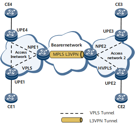
As shown in Figure 1, a user has many scattered sites on the access network of a carrier, and they are connected through Ethernet. These sites are required to interconnect to form an integrated network. In this case, the VPLS can be deployed on the access network to network those sites, and to access the MPLS L3VPN service running on the bearer network. If there are many scattered sites on the access network, deploy the HVPLS on it, as shown in the access network 2 in Figure 1. The network provider edge (NPE) works as provider edge (PE) at upper layer and UPEs as PE at lower layer. Therefore, the logical connections between PEs are reduced.
Pre-configuration Tasks
Before configuring a VPLS to access an L3VPN, complete the following tasks:
Connecting the interfaces and configuring their physical parameters so as to make their physical layer Up
Enabling IGP on the MPLS access network to realize IP connectivity
Creating full-mesh VPLS between UPEs and NPEs
Enabling IGP on the MPLS bearer network to realize IP connectivity
Configuring the basic functions of L3VPN on NPEs
- Creating VE Interfaces
- This part describes how to configure an L2VE interface that terminates the L2VPN and configure an L3VE interface that access L3VPN, and how to bind the VE interfaces to the relevant VE-Group.
- Creating an L2VE Interface
- This section describes how to configure an L2VE interface to terminate an L2VPN and how to bind the L2VE interface to a VE-Group.
- Creating an L3VE Interface
- This section describes how to configure an L3VE interface to access an L3VPN and how to bind the L3VE interface to a VE-Group.
- (Optional) Configuring the MAC Addresses of the L2VE interface and the L3VE interface
- If the MAC address of the L2VE interface or the L3VE interface is the same as that of other interface, you can configure a new MAC address for the L2VE interface or the L3VE interface.
- Binding a VSI to the L2VE Interface
- Take the L2VE interface as Attachment Circuit (AC) interface when binding a VSI to the L2VE interface.
- Configuring the Access to the Public Network or an L3VPN
- The configuration of an L3VE interface that accesses the public network or MPLS L3VPN varies with the networking environments.
- Verifying the Configuration of a VPLS to Access the Public Network or an L3VPN
- After configuring a VPLS network to access the public network or L3VPN successfully, you can view the binding relationship between the VE interface and the VE-Group, and information about VPLS VSIs.