Example for Configuring a Backup Device to Forward Multicast Data Flows Through a Backup Link
This section provides an example for configuring a backup device to forward multicast data flows through a backup link on a VPLS network. With this configuration, the backup device can forward multicast data flows immediately after the master device or primary link fails, improving service transmission reliability and minimizing service loss.
Networking Requirements
Reliable data, voice, and video transmission is important in Internet services. Backup devices and links are generally deployed to prevent service transmission interruptions.
Primary PW: PW between SPE1 and the UPE. This PW forwards multicast protocol and data packets when it is active.
Backup PW: PW between SPE2 and the UPE. Multicast protocol and data packets are blocked on the backup PW, disabling SPE2 from learning multicast forwarding entries.

On this example network, the UPE, SPE1, and SPE2 are Layer 2 devices on which the function to allow a backup device to forward multicast data flows through a backup link needs to be configured.
Without this function, multicast services will be interrupted for a long time when the primary link or master device fails. This is because the backup device does not create multicast forwarding entries when the master device works properly.
To minimize service interruptions, configure the function to allow a backup device to forward multicast data flows through a backup link. This function enables SPE2 to learn Layer 2 multicast forwarding entries, so that the backup PW can forward multicast data flows immediately when it becomes the primary PW.
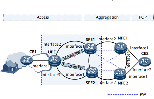
Interfaces 1 through 4 in this example represent GE 0/1/0, GE 0/1/1, GE 0/1/2, and GE 0/1/3, respectively.
Device |
Interface |
IP Address |
|---|---|---|
UPE |
GE 0/1/0 |
- |
GE 0/1/1 |
192.168.10.1/24 |
|
GE 0/1/2 |
192.168.20.1/24 |
|
Loopback 1 |
1.1.1.1/32 |
|
SPE1 |
GE 0/1/0 |
192.168.10.2/24 |
GE 0/1/1 |
192.168.30.1/24 |
|
Loopback 1 |
2.2.2.2/32 |
|
SPE2 |
GE 0/1/0 |
192.168.20.2/24 |
GE 0/1/1 |
192.168.50.1/24 |
|
Loopback 1 |
3.3.3.3/32 |
|
NPE1 |
GE 0/1/0 |
- |
GE 0/1/1 |
192.168.30.2/24 |
|
GE 0/1/3 |
192.168.60.1/24 |
|
Loopback 1 |
4.4.4.4/32 |
|
NPE2 |
GE 0/1/0 |
- |
GE 0/1/1 |
192.168.50.2/24 |
|
GE 0/1/3 |
192.168.60.2/24 |
|
Loopback 1 |
5.5.5.5/32 |
Configuration Roadmap
The configuration roadmap is as follows:
- Assign an IP address to each interface.
- Configure routing protocols to implement network-layer interconnection between PEs. In this example, OSPF is used.
Configure MPLS and public tunnels.
In this example, LDP LSPs are used as tunnels between PEs.
- Enable MPLS and MPLS LDP globally on each PE.
- Enable MPLS on interfaces of each PE.
- Enable MPLS LDP on the ingress and egress interfaces of each LDP LSP.
Configure PWs as follows:
- Enable MPLS L2VPN on each PE.
- Create a VSI on each PE.
- Specify the VSI peer on each PE. Configure two spoke PWs between the UPE and SPEs. Configure four hub PWs between the SPEs and NPEs.
Add the PWs between the UPE and SPEs to a PW protection group for the two PWs to work in backup mode as follows:
- Configure a PW protection group on the UPE.
- Configure the master/slave PW redundancy mode.
- Add the PWs to the PW protection group and specify the priorities of the PWs.
- Set the revertive switching delay to 60s.
Enable IGMP snooping globally and IGMP snooping for specific VSIs.
- Configure the function to allow a backup device to forward multicast data flows through a backup link as follows:
Configure the master and backup SPEs to send to the UPE IGMP Query messages through the PWs.
Configure the master and backup SPEs to receive from the UPE IGMP Report/Leave messages through the PWs.
Data Preparation
To complete the configuration, you need the following data:
IP address, OSPF process ID, and OSPF area ID of each interface
LSR ID of each node and the names and numbers of the interfaces on which LDP sessions are to be set up
VSI name, member discovery mode, VSI signaling type, VSI ID, VSI peer IP address, AC interface types, and AC interface numbers
PW protection group name, PW redundancy mode, revertive switching mode, revertive switching delay, and PW priorities
Procedure
- Assign an IP address to each interface on the backbone network.
- Configure routing protocols to implement network-layer interconnection among devices.
Configure OSPF on the UPE, SPEs, and NPEs to advertise the network segments and host routes of LSR IDs.
# Configure the UPE.
<UPE> system-view
[~UPE] ospf
[*UPE-ospf-1] area 0
[*UPE-ospf-1-area-0.0.0.0] network 1.1.1.1 0.0.0.0
[*UPE-ospf-1-area-0.0.0.0] network 192.168.10.0 0.0.0.255
[*UPE-ospf-1-area-0.0.0.0] network 192.168.20.0 0.0.0.255
[*UPE-ospf-1-area-0.0.0.0] quit
[*UPE-ospf-1] quit
[*UPE] commit
# Configure the SPEs. The following example uses SPE1. The configuration on SPE2 is similar.
<SPE1> system-view
[~SPE1] ospf
[*SPE1-ospf-1] area 0
[*SPE1-ospf-1-area-0.0.0.0] network 2.2.2.2 0.0.0.0
[*SPE1-ospf-1-area-0.0.0.0] network 192.168.10.0 0.0.0.255
[*SPE1-ospf-1-area-0.0.0.0] network 192.168.30.0 0.0.0.255
[*SPE1-ospf-1-area-0.0.0.0] quit
[*SPE1-ospf-1] quit
[*SPE1] commit
# Configure the NPEs. The following example uses NPE1. The configuration on NPE2 is similar.
<NPE1> system-view
[~NPE1] ospf
[*NPE1-ospf-1] area 0
[*NPE1-ospf-1-area-0.0.0.0] network 4.4.4.4 0.0.0.0
[*NPE1-ospf-1-area-0.0.0.0] network 192.168.30.0 0.0.0.255
[*NPE1-ospf-1-area-0.0.0.0] network 192.168.60.0 0.0.0.255
[*NPE1-ospf-1-area-0.0.0.0] quit
[*NPE1-ospf-1] quit
[*NPE1] commit
- Configure basic MPLS functions and set up local MPLS LDP sessions.
# Configure the UPE.
[~UPE] mpls lsr-id 1.1.1.1
[*UPE] mpls
[*UPE-mpls] quit
[*UPE] mpls ldp
[*UPE-ldp] quit
[*UPE] interface gigabitethernet 0/1/1
[*UPE-GigabitEthernet0/1/1] mpls
[*UPE-GigabitEthernet0/1/1] mpls ldp
[*UPE-GigabitEthernet0/1/1] quit
[*UPE] interface gigabitethernet 0/1/2
[*UPE-GigabitEthernet0/1/2] mpls
[*UPE-GigabitEthernet0/1/2] mpls ldp
[*UPE-GigabitEthernet0/1/2] quit
[*UPE] commit
# Configure the SPEs. The following example uses SPE1. The configuration on SPE2 is similar.
[~SPE1] mpls lsr-id 2.2.2.2
[*SPE1] mpls
[*SPE1-mpls] quit
[*SPE1] mpls ldp
[*SPE1-ldp] quit
[*SPE1] interface gigabitethernet 0/1/0
[*SPE1-GigabitEthernet0/1/0] mpls
[*SPE1-GigabitEthernet0/1/0] mpls ldp
[*SPE1-GigabitEthernet0/1/0] quit
[*SPE1] interface gigabitethernet 0/1/1
[*SPE1-GigabitEthernet0/1/1] mpls
[*SPE1-GigabitEthernet0/1/1] mpls ldp
[*SPE1-GigabitEthernet0/1/1] quit
[*SPE1] commit
# Configure the NPEs. The following example uses NPE1. The configuration on NPE2 is similar.
[~NPE1] mpls lsr-id 4.4.4.4
[*NPE1] mpls
[*NPE1-mpls] quit
[*NPE1] mpls ldp
[*NPE1-ldp] quit
[*NPE1] interface gigabitethernet 0/1/1
[*NPE1-GigabitEthernet0/1/1] mpls
[*NPE1-GigabitEthernet0/1/1] mpls ldp
[*NPE1-GigabitEthernet0/1/1] quit
[*NPE1] interface gigabitethernet 0/1/3
[*NPE1-GigabitEthernet0/1/3] mpls
[*NPE1-GigabitEthernet0/1/3] mpls ldp
[*NPE1-GigabitEthernet0/1/3] quit
[*NPE1] commit
- Configure PWs.
# Create a VSI on the UPE and specify SPE1 and SPE2 as the VSI peers.
<UPE> system-view
# Enable MPLS L2VPN.
[~UPE] mpls l2vpn
[*UPE-l2vpn] quit
# Create a VSI on the UPE and configure the LDP signaling type and VSI ID.
[~UPE] vsi vsi1 static
[*UPE-vsi-vsi1] pwsignal ldp
[*UPE-vsi-vsi1-ldp] vsi-id 1
# Specify VSI peers so that two PWs can be established between the UPE and SPEs.
[*UPE-vsi-vsi1-ldp] peer 2.2.2.2
[*UPE-vsi-vsi1-ldp] peer 3.3.3.3
[*UPE-vsi-vsi1-ldp] quit
[*UPE-vsi-vsi1] quit
[*UPE] commit
You do not need to specify the secondary parameter for the backup PW, because the PW protection group determines the primary/backup status of PWs based on PW priorities.
# Create a VSI on each SPE and specify the UPE and NPEs as VSI peers. The following example uses SPE1. The configuration on SPE2 is similar.
<SPE1> system-view
[~SPE1] mpls l2vpn
[*SPE1-l2vpn] quit
[*SPE1] vsi vsi1 static
[*SPE1-vsi-vsi1] pwsignal ldp
[*SPE1-vsi-vsi1-ldp] vsi-id 1
[*SPE1-vsi-vsi1-ldp] peer 1.1.1.1 upe
[*SPE1-vsi-vsi1-ldp] peer 4.4.4.4
[*SPE1-vsi-vsi1-ldp] peer 5.5.5.5
[*SPE1-vsi-vsi1-ldp] quit
[*SPE1-vsi-vsi1] quit
[*SPE1] commit
# Create a VSI on each NPE and specify the SPEs as VSI peers. The following example uses NPE1. The configuration on NPE2 is similar.
<NPE1> system-view
[~NPE1] mpls l2vpn
[*NPE1-l2vpn] quit
[*NPE1] vsi vsi1 static
[*NPE1-vsi-vsi1] pwsignal ldp
[*NPE1-vsi-vsi1-ldp] vsi-id 1
[*NPE1-vsi-vsi1-ldp] peer 2.2.2.2
[*NPE1-vsi-vsi1-ldp] peer 3.3.3.3
[*NPE1-vsi-vsi1-ldp] quit
[*NPE1-vsi-vsi1] quit
[*NPE1] commit
- Add the PWs between the UPE and SPEs to a PW protection group.
# Configure a PW protection group on the UPE and configure the PW redundancy mode as master/slave. Add the PWs to the PW protection group and specify the priorities of the PWs. Set the revertive switching delay to 60s.
[~UPE] vsi vsi1 static
[*UPE-vsi-vsi1] pwsignal ldp
[*UPE-vsi-vsi1-ldp] protect-group vsi1
[*UPE-vsi-vsi1-ldp-protect-group-vsi1] protect-mode pw-redundancy master
[*UPE-vsi-vsi1-ldp-protect-group-vsi1] peer 2.2.2.2 preference 1
[*UPE-vsi-vsi1-ldp-protect-group-vsi1] peer 3.3.3.3 preference 2
[*UPE-vsi-vsi1-ldp-protect-group-vsi1] reroute delay 60
[*UPE-vsi-vsi1-ldp-protect-group-vsi1] quit
[*UPE-vsi-vsi1-ldp] quit
[*UPE-vsi-vsi1] quit
[*UPE] commit
Before adding PWs to a PW protection group, ensure that the PW protection group already exists and its PW redundancy mode is specified. The revertive switching policy can be configured for only PW protection groups with the master/slave PW redundancy mode.
- Enable IGMP snooping in the system view and VSI view on the UPE and SPEs.
# Configure the UPE.
[~UPE] igmp-snooping enable
[*UPE] vsi vsi1
[*UPE-VSI-vsi1] igmp-snooping enable
[*UPE-VSI-vsi1] quit
[*UPE] commit
# Configure the SPEs. The following example uses SPE1. The configuration on SPE2 is similar.
[~SPE1] igmp-snooping enable
[*SPE1] vsi vsi1
[*SPE1-VSI-vsi1] igmp-snooping enable
[*SPE1-VSI-vsi1] quit
[*SPE1] commit
- Enable the UPE and SPEs to forward multicast data flows through the backup link.
# Configure the UPE.
[~UPE] vsi vsi1
[*UPE-vsi-vsi1] l2-multicast backup-query forward source-mac-replace
[*UPE-vsi-vsi1] l2-multicast backup-report forward source-mac-replace
[*UPE-vsi-vsi1] quit
[*UPE] commit
# Configure the SPEs. The following example uses SPE1. The configuration on SPE2 is similar.
[~SPE1] vsi vsi1
[*SPE1-vsi-vsi1] l2-multicast backup-query forward source-mac-replace
[*SPE1-vsi-vsi1] l2-multicast backup-report forward source-mac-replace
[*SPE1-vsi-vsi1] quit
[*SPE1] commit
- Verify the configuration.
Run the display vsi name protect-group command on the UPE to check PW protection group information. The command output shows that the forwarding state is Active for the primary PW and Inactive for the backup PW.
[~UPE] display vsi name vsi1 protect-group vsi1

Protect-group: vsi1
-------------------------------------------------------------------------------
PeerIp:VcId                Pref   Active
-------------------------------------------------------------------------------
2.2.2.2:1                  1      Active
3.3.3.3:1                  2      Inactive
Run the display vsi name vsi1 verbose command on the UPE to check information about the VSI and corresponding PWs. The command output shows that VSI State is up, PW State is up for the primary PW, and PW State is backup for the backup PW.
[~UPE] display vsi name vsi1 verbose
 ***VSI Name               : vsi1
    Administrator VSI      : no
    Isolate Spoken         : disable
    VSI Index              : 0
    PW Signaling           : ldp
    Member Discovery Style : static
    Bridge-domain Mode     : disable
    PW MAC Learning Style  : unqualify
    Encapsulation Type     : vlan
    MTU                    : 1500
    Diffserv Mode          : uniform
    Service Class          : --
    Color                  : --
    DomainId               : 255
    Domain Name            :
    Ignore AcState         : disable
    P2P VSI                : disable
    Create Time            : 0 days, 1 hours, 2 minutes, 50 seconds
    VSI State              : up

    VSI ID                 : 1
   *Peer Router ID         : 2.2.2.2
    primary or secondary   : primary
    Protect group          : vsi1
    Priority               : 1
    Active state           : active
    ignore-standby-state   : no
    VC Label               : 1024
    Peer Type              : dynamic
    Session                : up
    Tunnel ID              : 0x800005
    Broadcast Tunnel ID    : 0x800005
    Broad BackupTunnel ID  : 0x0
    CKey                   : 2
    NKey                   : 1
    Stp Enable             : 0
    PwIndex                : 0
    Control Word           : disable
   *Peer Router ID         : 3.3.3.3
    primary or secondary   : primary
    Protect group          : vsi1
    Priority               : 2
    Active state           : inactive
    ignore-standby-state   : no
    VC Label               : 1025
    Peer Type              : dynamic
    Session                : up
    Tunnel ID              : 0x800008
    Broadcast Tunnel ID    : 0x800008
    Broad BackupTunnel ID  : 0x0
    CKey                   : 4
    NKey                   : 3
    Stp Enable             : 0
    PwIndex                : 0
    Control Word           : disable
    Interface Name         : GigabitEthernet0/1/0.10
    State                  : up
    Access Port            : false
    Last Up Time           : 2011/12/16 15:14:40
    Total Up Time          : 0 days, 0 hours, 26 minutes, 16 seconds

  **PW Information:

   *Peer Ip Address        : 2.2.2.2
    PW State               : up
    Local VC Label         : 1024
    Remote VC Label        : 1024
    Remote Control Word    : disable
    PW Type                : label
    Tunnel ID              : 0x800005
    Broadcast Tunnel ID    : 0x800005
    Broad BackupTunnel ID  : 0x0
    Ckey                   : 0x2
    Nkey                   : 0x1
    Main PW Token          : 0x800005
    Slave PW Token         : 0x0
    Tnl Type               : LSP
    OutInterface           : GigabitEthernet0/1/1
    Backup OutInterface    :
    Stp Enable             : 0
    PW Last Up Time        : 2011/12/16 15:14:40
    PW Total Up Time       : 0 days, 0 hours, 26 minutes, 16 seconds
   *Peer Ip Address        : 3.3.3.3
    PW State               : backup
    Local VC Label         : 1025
    Remote VC Label        : 1024
    Remote Control Word    : disable
    PW Type                : label
    Tunnel ID              : 0x800008
    Broadcast Tunnel ID    : 0x800008
    Broad BackupTunnel ID  : 0x0
    Ckey                   : 0x4
    Nkey                   : 0x3
    Main PW Token          : 0x800008
    Slave PW Token         : 0x0
    Tnl Type               : LSP
    OutInterface           : GigabitEthernet0/1/2
    Backup OutInterface    :
    Stp Enable             : 0
    PW Last Up Time        : 2011/12/16 15:14:40
    PW Total Up Time       : 0 days, 0 hours, 26 minutes, 17 seconds
If the primary PW between the UPE and SPE1 fails, service traffic will be switched to the backup PW between the UPE and SPE2 for transmission.
Run the display vpls forwarding-info vsi command on the UPE. The command output shows that PW State is up for the backup PW and backup for the primary PW.
[~UPE] display vpls forwarding-info vsi vsi1
Total Number   : 2,        2  up,  0  down

Vsi-Name                        PeerIP          VcOrSiteId  PwState
vsi1                            2.2.2.2         1           BACKUP
vsi1                            3.3.3.3         1           UP
If the primary PW between the UPE and SPE1 recovers, service traffic will be switched back to the primary PW after the specified revertive switching delay expires.
Run the display vpls forwarding-info vsi command on the UPE. The command output shows that PW State is up for the primary PW and backup for the backup PW.
[~UPE] display vpls forwarding-info vsi vsi1
Total Number   : 2,        2  up,  0  down

Vsi-Name                        PeerIP          VcOrSiteId  PwState
vsi1                            3.3.3.3         1           BACKUP
vsi1                            2.2.2.2         1           UP
Configuration Files
UPE configuration file
#
sysname UPE
#
igmp-snooping enable
#
mpls lsr-id 1.1.1.1
#
mpls
#
mpls l2vpn
#
vsi vsi1 static
 pwsignal ldp
  vsi-id 1
  peer 2.2.2.2
  peer 3.3.3.3
  protect-group vsi1
   protect-mode pw-redundancy master
   reroute delay 60
   peer 2.2.2.2 preference 1
   peer 3.3.3.3 preference 2
 igmp-snooping enable
 l2-multicast backup-query forward
 l2-multicast backup-report forward
#
mpls ldp
#
interface GigabitEthernet0/1/0
 undo shutdown
#
interface GigabitEthernet0/1/1
 undo shutdown
 ip address 192.168.10.1 255.255.255.0
 mpls
 mpls ldp
#
interface GigabitEthernet0/1/2
 undo shutdown
 ip address 192.168.20.1 255.255.255.0
 mpls
 mpls ldp
#
interface LoopBack1
 ip address 1.1.1.1 255.255.255.255
#
ospf 1
 area 0.0.0.0
  network 1.1.1.1 0.0.0.0
  network 192.168.10.0 0.0.0.255
  network 192.168.20.0 0.0.0.255
#
return
SPE1 configuration file
#
sysname SPE1
#
igmp-snooping enable
#
mpls lsr-id 2.2.2.2
#
mpls
#
mpls l2vpn
#
vsi vsi1 static
 pwsignal ldp
  vsi-id 1
  peer 1.1.1.1 upe
  peer 4.4.4.4
  peer 5.5.5.5
 igmp-snooping enable
 l2-multicast backup-query forward
 l2-multicast backup-report forward
#
mpls ldp
#
interface GigabitEthernet0/1/0
 undo shutdown
 ip address 192.168.10.2 255.255.255.0
 mpls
 mpls ldp
#
interface GigabitEthernet0/1/1
 undo shutdown
 ip address 192.168.30.1 255.255.255.0
 mpls
 mpls ldp
#
interface LoopBack1
 ip address 2.2.2.2 255.255.255.255
#
ospf 1
 area 0.0.0.0
  network 2.2.2.2 0.0.0.0
  network 192.168.10.0 0.0.0.255
  network 192.168.30.0 0.0.0.255
#
return
SPE2 configuration file
#
sysname SPE2
#
igmp-snooping enable
#
mpls lsr-id 3.3.3.3
#
mpls
#
mpls l2vpn
#
vsi vsi1 static
 pwsignal ldp
  vsi-id 1
  peer 1.1.1.1 upe
  peer 4.4.4.4
  peer 5.5.5.5
 igmp-snooping enable
 l2-multicast backup-query forward
 l2-multicast backup-report forward
#
mpls ldp
#
interface GigabitEthernet0/1/0
 undo shutdown
 ip address 192.168.20.2 255.255.255.0
 mpls
 mpls ldp
#
interface GigabitEthernet0/1/1
 undo shutdown
 ip address 192.168.50.1 255.255.255.0
 mpls
 mpls ldp
#
interface LoopBack1
 ip address 3.3.3.3 255.255.255.255
#
ospf 1
 area 0.0.0.0
  network 3.3.3.3 0.0.0.0
  network 192.168.20.0 0.0.0.255
  network 192.168.50.0 0.0.0.255
#
return
NPE1 configuration file
#
sysname NPE1
#
mpls lsr-id 4.4.4.4
#
mpls
#
mpls l2vpn
#
vsi vsi1 static
 pwsignal ldp
  vsi-id 1
  peer 2.2.2.2
  peer 3.3.3.3
#
mpls ldp
#
interface GigabitEthernet0/1/0
 undo shutdown
 eth-trunk 10
#
interface GigabitEthernet0/1/1
 undo shutdown
 ip address 192.168.30.2 255.255.255.0
 mpls
 mpls ldp
#
interface GigabitEthernet0/1/3
 undo shutdown
 ip address 192.168.60.1 255.255.255.0
 mpls
 mpls ldp
#
interface LoopBack1
 ip address 4.4.4.4 255.255.255.255
#
ospf 1
 area 0.0.0.0
  network 4.4.4.4 0.0.0.0
  network 192.168.30.0 0.0.0.255
  network 192.168.60.0 0.0.0.255
#
return
NPE2 configuration file
#
sysname NPE2

#
mpls lsr-id 5.5.5.5
#
mpls
#
mpls l2vpn
#
vsi vsi1
 pwsignal ldp
  vsi-id 1
  peer 2.2.2.2
  peer 3.3.3.3
#
mpls ldp
#
interface GigabitEthernet0/1/0
 undo shutdown
#
interface GigabitEthernet0/1/1
 undo shutdown
 ip address 192.168.50.2 255.255.255.0
 mpls
 mpls ldp
#
interface GigabitEthernet0/1/3
 undo shutdown
 ip address 192.168.60.2 255.255.255.0
 mpls
 mpls ldp
#
interface LoopBack1
 ip address 5.5.5.5 255.255.255.255
#
ospf 1
 area 0.0.0.0
  network 5.5.5.5 0.0.0.0
  network 192.168.50.0 0.0.0.255
  network 192.168.60.0 0.0.0.255
#
return