Example for Configuring Dynamic BFD for SR-MPLS TE LSP
This section provides an example for configuring dynamic BFD for SR-MPLS TE LSP. Dynamic BFD for SR-MPLS TE LSP rapidly detects faults of SR-MPLS TE LSPs, which protects traffic transmitted on SR-MPLS TE LSPs.
Networking Requirements
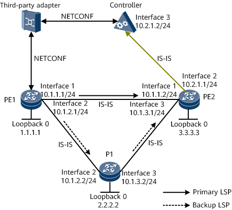
On the network shown in Figure 1, a tunnel as well as primary and backup LSPs for the tunnel need to be established from PE1 to PE2. The SR protocol is used for path generation and data forwarding. PE2 collects network topology information and reports the information to the controller using BGP-LS. The controller uses the information to calculate the primary and backup LSPs and delivers LSP information to a third-party adapter, and the third-party adapter forwards the LSP information to the ingress PE1.
Hot standby is enabled for the tunnel. If the primary LSP fails, traffic is switched to the backup LSP. After the primary LSP recovers, traffic is switched back.

You do not need to configure a PCE client (PCC) because the third-party adapter delivers the path information.
If a Huawei device connects to a non-Huawei device that does not support BFD, configure one-arm BFD to detect links.
Configuration Roadmap
The configuration roadmap is as follows:
Assign an IP address and a mask to each interface, and configure a loopback address as an MPLS LSR ID on each node.
Configure LSR IDs and enable MPLS TE globally and on interfaces on each LSR.
Enable SR globally on each node.
Configure a label allocation mode and a topology information collection mode. In this example, the controller collects assigns labels to forwarders.
Establish a BGP-LS peer relationship between PE2 and the controller so that PE2 can report network topology information to the controller using BGP-LS.
Configure a tunnel interface on the ingress PE1, and specify an IP address, tunneling protocol, destination IP address, and tunnel bandwidth.
Configure CR-LSP hot standby.
Enable BFD on the ingress PE1, configure BFD for MPLS TE, and set the minimum intervals at which BFD packets are sent and received and the local detection multiplier
Enable the egress to passively create a BFD session.
Data Preparation
To complete the configuration, you need the following data:
IP address of each interface, as shown in Figure 1
IS-IS process ID: 1; IS-IS system ID of each node: converted from the loopback 0 address; IS-IS level: level-2
BGP-LS peer relationship between the controller and PE2, as shown in Figure 1
Name of a BFD session
Local and remote discriminators of the BFD session
Procedure
- Assign an IP address and a mask to each interface.
# Configure PE1.
<HUAWEI> system-view
[~HUAWEI] sysname PE1
[*HUAWEI] commit
[~PE1] interface loopback 0
[*PE1-LoopBack0] ip address 1.1.1.1 32
[*PE1-LoopBack0] quit
[*PE1] interface gigabitethernet0/1/0
[*PE1-GigabitEthernet0/1/0] ip address 10.1.1.1 24
[*PE1-GigabitEthernet0/1/0] quit
[*PE1] interface gigabitethernet0/1/8
[*PE1-GigabitEthernet0/1/8] ip address 10.1.2.1 24
[*PE1-GigabitEthernet0/1/8] quit
[*PE1] commit
# Configure P1.
<HUAWEI> system-view
[~HUAWEI] sysname P1
[*HUAWEI] commit
[~P1] interface loopback 0
[*P1-LoopBack0] ip address 2.2.2.2 32
[*P1-LoopBack0] quit
[*P1] interface gigabitethernet0/1/8
[*P1-GigabitEthernet0/1/8] ip address 10.1.2.2 24
[*P1-GigabitEthernet0/1/8] quit
[*P1] interface gigabitethernet0/1/16
[*P1-GigabitEthernet0/1/16] ip address 10.1.3.2 24
[*P1-GigabitEthernet0/1/16] quit
[*P1] commit
# Configure PE2.
<HUAWEI> system-view
[~HUAWEI] sysname PE2
[*HUAWEI] commit
[~PE2] interface loopback 0
[*PE2-LoopBack0] ip address 3.3.3.3 32
[*PE2-LoopBack0] quit
[*PE2] interface gigabitethernet0/1/0
[*PE2-GigabitEthernet0/1/0] ip address 10.1.1.2 24
[*PE2-GigabitEthernet0/1/0] quit
[*PE2] interface gigabitethernet0/1/8
[*PE2-GigabitEthernet0/1/8] ip address 10.2.1.1 24
[*PE2-GigabitEthernet0/1/8] quit
[*PE2] interface gigabitethernet0/1/16
[*PE2-GigabitEthernet0/1/16] ip address 10.1.3.1 24
[*PE2-GigabitEthernet0/1/16] quit
[*PE2] commit
- Configure IS-IS to advertise the route to each network segment to which each interface is connected and to advertise the host route to each loopback address that is used as an LSR ID.
# Configure PE1.
[~PE1] isis 1
[*PE1-isis-1] is-level level-2
[*PE1-isis-1] network-entity 10.0000.0000.0002.00
[*PE1-isis-1] quit
[*PE1] interface loopback 0
[*PE1-LoopBack0] isis enable 1
[*PE1-LoopBack0] quit
[*PE1] interface gigabitethernet0/1/0
[*PE1-GigabitEthernet0/1/0] isis enable 1
[*PE1-GigabitEthernet0/1/0] quit
[*PE1] interface gigabitethernet0/1/8
[*PE1-GigabitEthernet0/1/8] isis enable 1
[*PE1-GigabitEthernet0/1/8] quit
[*PE1] commit
# Configure P1.
[~P1] isis 1
[*P1-isis-1] is-level level-2
[*P1-isis-1] network-entity 10.0000.0000.0003.00
[*P1-isis-1] quit
[*P1] interface loopback 0
[*P1-LoopBack0] isis enable 1
[*P1-LoopBack0] quit
[*P1] interface gigabitethernet0/1/8
[*P1-GigabitEthernet0/1/8] isis enable 1
[*P1-GigabitEthernet0/1/8] quit
[*P1] interface gigabitethernet0/1/16
[*P1-GigabitEthernet0/1/16] isis enable 1
[*P1-GigabitEthernet0/1/16] quit
[*P1] commit
# Configure PE2.
[~PE2] isis 1
[*PE2-isis-1] is-level level-2
[*PE2-isis-1] network-entity 10.0000.0000.0004.00
[*PE2-isis-1] quit
[*PE2] interface loopback 0
[*PE2-LoopBack0] isis enable 1
[*PE2-LoopBack0] quit
[*PE2] interface gigabitethernet0/1/0
[*PE2-GigabitEthernet0/1/0] isis enable 1
[*PE2-GigabitEthernet0/1/0] quit
[*PE2] interface gigabitethernet0/1/16
[*PE2-GigabitEthernet0/1/16] isis enable 1
[*PE2-GigabitEthernet0/1/16] quit
[*PE2] commit
- Establish a BGP-LS peer relationship between the controller and PE2.
Establish a BGP-LS peer relationship between the controller and PE2 so that PE2 can report network topology information to the controller using BGP-LS. This example uses the configuration of PE2. For controller configuration details, see Configuration Files in this section.
[~PE2] isis 1
[*PE2-isis-1] bgp-ls enable level-2
[*PE2-isis-1] quit
[*PE2] bgp 100
[*PE2-bgp] peer 10.2.1.2 as-number 100
[*PE2-bgp] link-state-family unicast
[*PE2-bgp-af-ls] peer 10.2.1.2 enable
[*PE2-bgp-af-ls] quit
[*PE2-bgp] quit
[*PE2] commit
- Configure basic MPLS functions and enable MPLS TE.
# Configure PE1.
[~PE1] mpls lsr-id 1.1.1.1
[*PE1] mpls
[*PE1-mpls] mpls te
[*PE1-mpls] quit
[*PE1] interface gigabitethernet 0/1/0
[*PE1-GigabitEthernet0/1/0] mpls
[*PE1-GigabitEthernet0/1/0] mpls te
[*PE1-GigabitEthernet0/1/0] quit
[*PE1] interface gigabitethernet0/1/8
[*PE1-GigabitEthernet0/1/8] mpls
[*PE1-GigabitEthernet0/1/8] mpls te
[*PE1-GigabitEthernet0/1/8] commit
[~PE1-GigabitEthernet0/1/8] quit
The configurations on P1 and PE2 are similar to the configuration on PE1. For configuration details, see Configuration Files in this section.
- Enable SR globally on each node.
# Configure PE1.
[~PE1] segment-routing
[*PE1-segment-routing] quit
[*PE1] commit
The configurations on P1 and PE2 are similar to the configuration on PE1. The configuration details are not provided.
- Configure a label allocation mode and a topology information collection mode. In this example, the controller collects assigns labels to forwarders.
# Configure PE1.
[~PE1] isis 1
[~PE1-isis-1] cost-style wide
[*PE1-isis-1] traffic-eng level-2
[*PE1-isis-1] segment-routing mpls
[*PE1-isis-1] commit
[~PE1-isis-1] quit
The configurations on P1 and PE2 are similar to the configuration on PE1. The configuration details are not provided.
- Configure a tunnel interface and hot standby on the ingress PE1.
# Configure PE1.
[~PE1] interface tunnel1
[*PE1-Tunnel1] ip address unnumbered interface loopback 0
[*PE1-Tunnel1] tunnel-protocol mpls te
[*PE1-Tunnel1] destination 3.3.3.3
[*PE1-Tunnel1] mpls te tunnel-id 1
[*PE1-Tunnel1] mpls te signal-protocol segment-routing
[*PE1-Tunnel1] mpls te pce delegate
[*PE1-Tunnel1] mpls te backup hot-standby
[*PE1-Tunnel1] commit
[~PE1-Tunnel1] quit
- Verify the configuration.
After completing the configuration, run the display mpls te tunnel-interface command on PE1. The tunnel interface is Up.
[~PE1] display mpls te tunnel-interface tunnel1
    Tunnel Name       : Tunnel1
    Signalled Tunnel Name: -
    Tunnel State Desc : CR-LSP is Up
    Tunnel Attributes   :
    Active LSP          : Primary LSP
    Traffic Switch      : -
    Session ID          : 1
    Ingress LSR ID      : 1.1.1.1               Egress LSR ID: 3.3.3.3
    Admin State         : UP                    Oper State   : UP
    Signaling Protocol  : Segment-Routing
    FTid                : 1
    Tie-Breaking Policy : None                  Metric Type  : None
    Bfd Cap             : None
    Reopt               : Disabled              Reopt Freq   : -
    Inter-area Reopt    : Disabled
    Auto BW             : Disabled              Threshold    : 0 percent
    Current Collected BW: 0 kbps                Auto BW Freq : 0
    Min BW              : 0 kbps                Max BW       : 0 kbps
    Offload             : Disabled              Offload Freq : -
    Low Value           : -                     High Value   : -
    Readjust Value      : -
    Offload Explicit Path Name: -
    Tunnel Group        : Primary
    Interfaces Protected: -
    Excluded IP Address : -
    Referred LSP Count  : 0
    Primary Tunnel      : -                     Pri Tunn Sum : -
    Backup Tunnel       : -
    Group Status        : Up                    Oam Status   : None
    IPTN InLabel        : -                     Tunnel BFD Status : -
    BackUp LSP Type     : Hot-Standby           BestEffort   : -
    Secondary HopLimit  : -
    BestEffort HopLimit  : -
    Secondary Explicit Path Name: -
    Secondary Affinity Prop/Mask: 0x0/0x0
    BestEffort Affinity Prop/Mask: -
    IsConfigLspConstraint: -
    Hot-Standby Revertive Mode:  Revertive
    Hot-Standby Overlap-path:  Disabled
    Hot-Standby Switch State:  CLEAR
    Bit Error Detection:  Disabled
    Bit Error Detection Switch Threshold:  -
    Bit Error Detection Resume Threshold:  -
    Ip-Prefix Name    : -
    P2p-Template Name : -
    PCE Delegate      : Active                LSP Control Status : Local control
    Path Verificaiton : No
    Entropy Label     : None
    Auto BW Remain Time : -                   Reopt Remain Time  : -
    Segment-Routing Remote Label    : -
    Metric Inherit IGP : None
    Binding Sid       : -                     Reverse Binding Sid : -
    FRR Attr Source   : -                     Is FRR degrade down : No

    Primary LSP ID      : 1.1.1.1:19
    LSP State           : UP                    LSP Type     : Primary
    Setup Priority      : 7                     Hold Priority: 7
    IncludeAll          : 0x0
    IncludeAny          : 0x0
    ExcludeAny          : 0x0
    Affinity Prop/Mask  : 0x0/0x0               Resv Style   :  SE
    Configured Bandwidth Information:
    CT0 Bandwidth(Kbit/sec): 10000           CT1 Bandwidth(Kbit/sec): 0
    CT2 Bandwidth(Kbit/sec): 0               CT3 Bandwidth(Kbit/sec): 0
    CT4 Bandwidth(Kbit/sec): 0               CT5 Bandwidth(Kbit/sec): 0
    CT6 Bandwidth(Kbit/sec): 0               CT7 Bandwidth(Kbit/sec): 0
    Actual Bandwidth Information:
    CT0 Bandwidth(Kbit/sec): 10000           CT1 Bandwidth(Kbit/sec): 0
    CT2 Bandwidth(Kbit/sec): 0               CT3 Bandwidth(Kbit/sec): 0
    CT4 Bandwidth(Kbit/sec): 0               CT5 Bandwidth(Kbit/sec): 0
    CT6 Bandwidth(Kbit/sec): 0               CT7 Bandwidth(Kbit/sec): 0
    Explicit Path Name  : -                                Hop Limit: -
    Record Route        : -                            Record Label : -
    Route Pinning       : -
    FRR Flag            : -
    IdleTime Remain     : -
    BFD Status          : -
    Soft Preemption     : -
    Reroute Flag        : -
    Pce Flag            : Normal
    Path Setup Type     : PCE
    Create Modify LSP Reason: -

    Backup LSP ID       : 1.1.1.1:46945
    IsBestEffortPath    : No
    LSP State           : UP                    LSP Type     : Hot-Standby
    Setup Priority      : 7                     Hold Priority: 7
    IncludeAll          : 0x0
    IncludeAny          : 0x0
    ExcludeAny          : 0x0
    Affinity Prop/Mask  : 0x0/0x0               Resv Style   :  SE
    Configured Bandwidth Information:
    CT0 Bandwidth(Kbit/sec): 0               CT1 Bandwidth(Kbit/sec): 0
    CT2 Bandwidth(Kbit/sec): 0               CT3 Bandwidth(Kbit/sec): 0
    CT4 Bandwidth(Kbit/sec): 0               CT5 Bandwidth(Kbit/sec): 0
    CT6 Bandwidth(Kbit/sec): 0               CT7 Bandwidth(Kbit/sec): 0
    Actual Bandwidth Information:
    CT0 Bandwidth(Kbit/sec): 0               CT1 Bandwidth(Kbit/sec): 0
    CT2 Bandwidth(Kbit/sec): 0               CT3 Bandwidth(Kbit/sec): 0
    CT4 Bandwidth(Kbit/sec): 0               CT5 Bandwidth(Kbit/sec): 0
    CT6 Bandwidth(Kbit/sec): 0               CT7 Bandwidth(Kbit/sec): 0
    Explicit Path Name  : -                                Hop Limit: -
    Record Route        : -                            Record Label : -
    Route Pinning       : -
    FRR Flag            : -
    IdleTime Remain     : -
    BFD Status          : -
    Soft Preemption     : -
    Reroute Flag        : -
    Pce Flag            : Normal
    Path Setup Type     : PCE
    Create Modify LSP Reason: -
Run the display mpls te tunnel command on PE1 to view SR-MPLS TE tunnel information.
[~PE1] display mpls te tunnel
* means the LSP is detour LSP
-------------------------------------------------------------------------------
Ingress LsrId   Destination     LSPID In/OutLabel     R Tunnel-name
-------------------------------------------------------------------------------
-               -               -     101/101         T lsp
1.1.1.1         3.3.3.3         21    -/330000        I Tunnel1
1.1.1.1         3.3.3.3         26    -/330002        I Tunnel1
-------------------------------------------------------------------------------
R: Role, I: Ingress, T: Transit, E: Egress
Run the display mpls te tunnel path command on PE1 to view path information on the SR-MPLS TE tunnel.
[~PE1] display mpls te tunnel path
Tunnel Interface Name : Tunnel1
Lsp ID : 1.1.1.1 :1 :21
Hop Information
Hop 0 Label 330000 NAI 10.1.1.2

Tunnel Interface Name : Tunnel1
Lsp ID : 1.1.1.1 :1 :26
Hop Information
Hop 0 Label 330002 NAI 10.1.2.2
Hop 1 Label 330002 NAI 10.1.3.1
- Enable BFD and configure BFD for MPLS TE on the ingress PE1.
# Enable BFD for MPLS TE on the tunnel interface of PE1. Set the minimum intervals at which BFD packets are sent and received to 100 ms and the local detection multiplier to 3.
[~PE1] bfd
[*PE1-bfd] quit
[*PE1] interface tunnel 1
[*PE1-Tunnel1] mpls te bfd enable
[*PE1-Tunenl1] mpls te bfd min-tx-interval 100 min-rx-interval 100 detect-multiplier 3
[*PE1-Tunenl1] commit
[~PE1-Tunenl1] quit
- Enable the egress to passively create a BFD session.
[~PE2] bfd
[*PE2-bfd] mpls-passive
[*PE2-bfd] commit
[~PE2-bfd] quit
# After completing the configuration, run the display bfd session mpls-te interface Tunnel command on PE1. The BFD session status is Up.
[~PE1] display bfd session mpls-te interface Tunnel 1 te-lsp
(w): State in WTR
(*): State is invalid
--------------------------------------------------------------------------------
Local      Remote     PeerIpAddr      State     Type        InterfaceName
--------------------------------------------------------------------------------
16399      16386      3.3.3.3         Up        D_TE_LSP    Tunnel1
--------------------------------------------------------------------------------
Configuration Files
PE1 configuration file
#
sysname PE1
#
bfd
#
mpls lsr-id 1.1.1.1
#
mpls
 mpls te
#
segment-routing
#
isis 1
 is-level level-2
 cost-style wide
 network-entity 10.0000.0000.0002.00
 traffic-eng level-2
 segment-routing mpls
#
interface GigabitEthernet0/1/0
 undo shutdown
 ip address 10.1.1.1 255.255.255.0
 isis enable 1
 mpls
 mpls te
#
interface GigabitEthernet0/1/8
 undo shutdown
 ip address 10.1.2.1 255.255.255.0
 isis enable 1
 mpls
 mpls te
#
interface LoopBack0
 ip address 1.1.1.1 255.255.255.255
 isis enable 1
#
 interface Tunnel1
 ip address unnumbered interface LoopBack0
 tunnel-protocol mpls te
 destination 3.3.3.3
 mpls te signal-protocol segment-routing
 mpls te backup hot-standby
 mpls te tunnel-id 1
 mpls te pce delegate
 mpls te bfd enable
 mpls te bfd min-tx-interval 100 min-rx-interval 100
#
return
P1 configuration file
#
sysname P1
#
mpls lsr-id 2.2.2.2
#
mpls
 mpls te
#
segment-routing
#
isis 1
 is-level level-2
 cost-style wide
 network-entity 10.0000.0000.0003.00
 traffic-eng level-2
 segment-routing mpls
#
interface GigabitEthernet0/1/8
 undo shutdown
 ip address 10.1.2.2 255.255.255.0
 isis enable 1
 mpls
 mpls te
#
interface GigabitEthernet0/1/16
 undo shutdown
 ip address 10.1.3.2 255.255.255.0
 isis enable 1
 mpls
 mpls te
#
interface LoopBack0
 ip address 2.2.2.2 255.255.255.255
 isis enable 1
#
return
PE2 configuration file
#
sysname PE2
#
bfd
 mpls-passive
#
mpls lsr-id 3.3.3.3
#
mpls
 mpls te
#
segment-routing
#
isis 1
 is-level level-2
 cost-style wide
 bgp-ls enable level-2
 network-entity 10.0000.0000.0004.00
 traffic-eng level-2
 segment-routing mpls
#
interface GigabitEthernet0/1/0
 undo shutdown
 ip address 10.1.1.2 255.255.255.0
 isis enable 1
 mpls
 mpls te
#
interface GigabitEthernet0/1/8
 undo shutdown
 ip address 10.2.1.1 255.255.255.0
 isis enable 1
#
interface GigabitEthernet0/1/16
 undo shutdown
 ip address 10.1.3.1 255.255.255.0
 isis enable 1
 mpls
 mpls te
#
interface LoopBack0
 ip address 3.3.3.3 255.255.255.255
 isis enable 1
#
bgp 100
 peer 10.2.1.2 as-number 100
 #
 ipv4-family unicast
  undo synchronization
  peer 10.2.1.2 enable
 #
 link-state-family unicast
  peer 10.2.1.2 enable
#
return
Controller configuration file
#
sysname Controller
#
isis 1
 is-level level-2
 cost-style wide
 network-entity 10.0000.0000.0005.00
 traffic-eng level-2
 segment-routing mpls
#
interface GigabitEthernet0/1/16
 undo shutdown
 ip address 10.2.1.2 255.255.255.0
 isis enable 1
#
return