Example for Configuring Static BFD for SR-MPLS TE
This section provides an example for configuring static BFD for SR-MPLS TE to implement rapid traffic switching if a tunnel fault occurs.
Networking Requirements
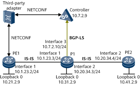
On the network shown in Figure 1, a tunnel and an LSP need to be established from PE1 to PE2. The SR protocol is used for path generation and data forwarding. PE1 and PE2 are the path's ingress and egress, respectively. P1 collects network topology information and reports the information to the controller using BGP-LS. The controller calculates an LSP based on the collected topology information and delivers the path information to a third-party adapter. The third-party adapter then sends the path information to PE1.

You do not need to configure a PCE client (PCC) because the third-party adapter delivers the path information.
If a Huawei device connects to a non-Huawei device that does not support BFD, configure one-arm BFD to detect links.
Configuration Roadmap
The configuration roadmap is as follows:
Assign an IP address and a mask to each interface, and configure a loopback address as an MPLS LSR ID on each node.
Configure LSR IDs and enable MPLS TE globally and on interfaces on each LSR.
Enable SR globally on each node.
Configure IS-IS TE on each node.
Establish a BGP-LS peer relationship between P1 and the controller so that P1 can report network topology information to the controller using BGP-LS.
Configure a tunnel interface on the ingress PE1, and specify an IP address, tunneling protocol, destination IP address, and tunnel bandwidth.
Configure a BFD session on PE1 to monitor the primary SR-MPLS TE tunnel.
Data Preparation
To complete the configuration, you need the following data:
IP address of each interface, as shown in Figure 1
IS-IS process ID: 1; IS-IS system ID of each node: converted from the loopback 0 address; IS-IS level: level-2
BGP-LS peer relationship between P1 and the controller, as shown in Figure 1
Name of a BFD session
Local and remote discriminators of the BFD session
Procedure
- Assign an IP address and a mask to each interface.
# Configure PE1.
<HUAWEI> system-view
[~HUAWEI] sysname PE1
[*HUAWEI] commit
[~PE1] interface loopback 0
[*PE1-LoopBack0] ip address 10.21.2.9 32
[*PE1-LoopBack0] quit
[*PE1] interface gigabitethernet0/1/0
[*PE1-GigabitEthernet0/1/0] ip address 10.1.23.2 24
[*PE1-GigabitEthernet0/1/0] quit
[*PE1] commit
# Configure P1.
<HUAWEI> system-view
[~HUAWEI] sysname P1
[*HUAWEI] commit
[~P1] interface loopback 0
[*P1-LoopBack0] ip address 10.31.2.9 32
[*P1-LoopBack0] quit
[*P1] interface gigabitethernet0/1/0
[*P1-GigabitEthernet0/1/0] ip address 10.1.23.3 24
[*P1-GigabitEthernet0/1/0] quit
[*P1] interface gigabitethernet0/1/8
[*P1-GigabitEthernet0/1/8] ip address 10.20.34.3 24
[*P1-GigabitEthernet0/1/8] quit
[*P1] interface gigabitethernet0/1/1
[*P1-GigabitEthernet0/1/1] ip address 10.7.2.10 24
[*P1-GigabitEthernet0/1/1] quit
[*P1] commit
# Configure PE2.
<HUAWEI> system-view
[~HUAWEI] sysname PE2
[*HUAWEI] commit
[~PE2] interface loopback 0
[*PE2-LoopBack0] ip address 10.41.2.9 32
[*PE2-LoopBack0] quit
[*PE2] interface gigabitethernet0/1/8
[*PE2-GigabitEthernet0/1/8] ip address 10.20.34.4 24
[*PE2-GigabitEthernet0/1/8] quit
[*PE2] commit
- Configure IS-IS to advertise the route to each network segment of each interface and to advertise the host route to each loopback address (used as an LSR ID).
# Configure PE1.
[~PE1] isis 1
[*PE1-isis-1] is-level level-2
[*PE1-isis-1] network-entity 11.1111.1111.1111.00
[*PE1-isis-1] quit
[*PE1] interface loopback 0
[*PE1-LoopBack0] isis enable 1
[*PE1-LoopBack0] quit
[*PE1] interface gigabitethernet0/1/0
[*PE1-GigabitEthernet0/1/0] isis enable 1
[*PE1-GigabitEthernet0/1/0] quit
[*PE1] commit
# Configure P1.
[~P1] isis 1
[*P1-isis-1] is-level level-2
[*P1-isis-1] network-entity 11.2222.2222.2222.00
[*P1-isis-1] quit
[*P1] interface loopback 0
[*P1-LoopBack0] isis enable 1
[*P1-LoopBack0] quit
[*P1] interface gigabitethernet0/1/0
[*P1-GigabitEthernet0/1/0] isis enable 1
[*P1-GigabitEthernet0/1/0] quit
[*P1] interface gigabitethernet0/1/8
[*P1-GigabitEthernet0/1/8] isis enable 1
[*P1-GigabitEthernet0/1/8] quit
[*P1] commit
# Configure PE2.
[~PE2] isis 1
[*PE2-isis-1] is-level level-2
[*PE2-isis-1] network-entity 11.3333.3333.3333.00
[*PE2-isis-1] quit
[*PE2] interface loopback 0
[*PE2-LoopBack0] isis enable 1
[*PE2-LoopBack0] quit
[*PE2] interface gigabitethernet0/1/8
[*PE2-GigabitEthernet0/1/8] isis enable 1
[*PE2-GigabitEthernet0/1/8] quit
[*PE2] commit
- Establish a BGP-LS peer relationship between P1 and the controller.
Establish a BGP-LS peer relationship between P1 and the controller so that P1 can report network topology information to the controller using BGP-LS. This example uses the configuration of P1. For controller configuration details, see Configuration Files in this section.
[~P1] isis 1
[*P1-isis-1] bgp-ls enable level-2
[*P1-isis-1] quit
[*P1] bgp 100
[*P1-bgp] peer 10.7.2.9 as-number 100
[*P1-bgp] link-state-family unicast
[*P1-bgp-af-ls] peer 10.7.2.9 enable
[*P1-bgp-af-ls] quit
[*P1-bgp] quit
[*P1] commit
- Configure basic MPLS functions and enable MPLS TE.
# Configure PE1.
[~PE1] mpls lsr-id 10.21.2.9
[*PE1] mpls
[*PE1-mpls] mpls te
[*PE1-mpls] quit
[*PE1] interface gigabitethernet 0/1/0
[*PE1-GigabitEthernet0/1/0] mpls
[*PE1-GigabitEthernet0/1/0] mpls te
[*PE1-GigabitEthernet0/1/0] commit
[~PE1-GigabitEthernet0/1/0] quit
The configurations except the LSR ID configuration on P1 and PE2 are the same as those on PE1.
- Enable SR globally on each node.
# Configure PE1.
[~PE1] segment-routing
[*PE1-segment-routing] quit
[*PE1] commit
The configurations on P1 and PE2 are similar to the configuration on PE1.
- Configure IS-IS TE on each node.
# Configure PE1.
[~PE1] isis 1
[~PE1-isis-1] cost-style wide
[*PE1-isis-1] traffic-eng level-2
[*PE1-isis-1] segment-routing mpls
[*PE1-isis-1] commit
[~PE1-isis-1] quit
The configuration on P1 and PE2 is the same as that on PE1.
- Configure a tunnel interface on PEs.
# Configure PE1.
[~PE1] interface Tunnel10
[*PE1-Tunnel10] ip address unnumbered interface loopback 0
[*PE1-Tunnel10] tunnel-protocol mpls te
[*PE1-Tunnel10] destination 10.41.2.9
[*PE1-Tunnel10] mpls te tunnel-id 1
[*PE1-Tunnel10] mpls te signal-protocol segment-routing
[*PE1-Tunnel10] commit
[~PE1-Tunnel10] quit
# Configure PE2.
[~PE2] interface Tunnel10
[*PE2-Tunnel10] ip address unnumbered interface loopback 0
[*PE2-Tunnel10] tunnel-protocol mpls te
[*PE2-Tunnel10] destination 10.21.2.9
[*PE2-Tunnel10] mpls te tunnel-id 2
[*PE2-Tunnel10] mpls te signal-protocol segment-routing
[*PE2-Tunnel10] commit
[~PE2-Tunnel10] quit
- Verify the configuration.
After completing the configuration, run the display interface tunnel command on PE1. You can check that the tunnel interface is Up.
Run the display mpls te tunnel command on each node to check MPLS TE tunnel establishment.
[~PE1] display mpls te tunnel
* means the LSP is detour LSP
------------------------------------------------------------------------------
Ingress LsrId    Destination      LSPID   In/Out Label     R  Tunnel-name
------------------------------------------------------------------------------
10.21.2.9        10.41.2.9        1       --/20            I  Tunnel10
-------------------------------------------------------------------------------
R: Role, I: Ingress, T: Transit, E: Egress
[~PE2] display mpls te tunnel
* means the LSP is detour LSP
------------------------------------------------------------------------------
Ingress LsrId    Destination      LSPID   In/Out Label     R  Tunnel-name
------------------------------------------------------------------------------
10.41.2.9        10.21.2.9        1       --/120           I  Tunnel10
-------------------------------------------------------------------------------
R: Role, I: Ingress, T: Transit, E: Egress
- Configure BFD for SR-MPLS TE.
# Configure a BFD session on PE1 to detect the SR-MPLS TE tunnel, and set the minimum intervals at which BFD packets are sent and received.
[~PE1] bfd
[*PE1-bfd] quit
[*PE1] bfd pe1tope2 bind mpls-te interface Tunnel10
[*PE1-bfd-lsp-session-pe1tope2] discriminator local 12
[*PE1-bfd-lsp-session-pe1tope2] discriminator remote 21
[*PE1-bfd-lsp-session-pe1tope2] min-tx-interval 100
[*PE1-bfd-lsp-session-pe1tope2] min-rx-interval 100
[*PE1-bfd-lsp-session-pe1tope2] commit
[~PE1-bfd-lsp-session-pe1tope2] quit
# Configure a BFD session on PE2 to detect the reverse SR-MPLS TE tunnel, and set the minimum intervals at which BFD packets are sent and received.
[~PE2] bfd
[*PE2-bfd] quit
[*PE2] bfd pe2tope1 bind mpls-te interface Tunnel10
[*PE2-bfd-lsp-session-pe2tope1] discriminator local 21
[*PE1-bfd-lsp-session-pe1tope2] discriminator remote 12
[*PE2-bfd-lsp-session-pe2tope1] min-tx-interval 100
[*PE2-bfd-lsp-session-pe2tope1] min-rx-interval 100
[*PE2-bfd-lsp-session-pe2tope1] commit
[~PE2-bfd-lsp-session-pe2tope1] quit
# After completing the configuration, run the display bfd session { all | discriminator discr-value | mpls-te interface interface-type interface-number } [ verbose ] command on PE1 and PE2. You can check that the BFD session is Up.
Configuration Files
PE1 configuration file
#
sysname PE1
#
bfd
#
mpls lsr-id 10.21.2.9
#
mpls
 mpls te
#
segment-routing
#
isis 1
 is-level level-2
 cost-style wide
 network-entity 11.1111.1111.1111.00
 traffic-eng level-2
 segment-routing mpls
#
interface GigabitEthernet0/1/0
 undo shutdown
 ip address 10.1.23.2 255.255.255.0
 isis enable 1
 mpls
 mpls te
#
interface LoopBack0
 ip address 10.21.2.9 255.255.255.255
 isis enable 1
#
interface Tunnel10
 ip address unnumbered interface LoopBack0
 tunnel-protocol mpls te
 destination 10.41.2.9
 mpls te signal-protocol segment-routing
 mpls te tunnel-id 1
#
bfd pe1tope2 bind mpls-te interface Tunnel10
 discriminator local 12
 discriminator remote 21
 min-tx-interval 100
 min-rx-interval 100
#
return
P1 configuration file
#
sysname P1
#
mpls lsr-id 10.31.2.9
#
mpls
 mpls te
#
segment-routing
#
isis 1
 is-level level-2
 cost-style wide
 bgp-ls enable level-2
 network-entity 11.2222.2222.2222.00
 traffic-eng level-2
 segment-routing mpls
#
interface GigabitEthernet0/1/0
 undo shutdown
 ip address 10.1.23.3 255.255.255.0
 isis enable 1
 mpls
 mpls te
#
interface GigabitEthernet0/1/1
 undo shutdown
 ip address 10.7.2.10 255.255.255.0
 isis enable 1
#
interface GigabitEthernet0/1/8
 undo shutdown
 ip address 10.20.34.3 255.255.255.0
 isis enable 1
 mpls
 mpls te
#
interface LoopBack0
 ip address 10.31.2.9 255.255.255.255
 isis enable 1
#
bgp 100
 peer 10.7.2.9 as-number 100
 #
 ipv4-family unicast
  undo synchronization
  peer 10.7.2.9 enable
 #
 link-state-family unicast
  peer 10.7.2.9 enable
#
return
PE2 configuration file
#
sysname PE2
#
bfd
#
mpls lsr-id 10.41.2.9
#
mpls
 mpls te
#
segment-routing
#
isis 1
 is-level level-2
 cost-style wide
 network-entity 11.3333.3333.3333.00
 traffic-eng level-2
 segment-routing mpls
#
interface GigabitEthernet0/1/8
 undo shutdown
 ip address 10.20.34.4 255.255.255.0
 isis enable 1
 mpls
 mpls te
#
interface LoopBack0
 ip address 10.41.2.9 255.255.255.255
 isis enable 1
#
interface Tunnel10
 ip address unnumbered interface LoopBack0
 tunnel-protocol mpls te
 destination 10.21.2.9
 mpls te signal-protocol segment-routing
 mpls te tunnel-id 2
#
bfd pe2tope1 bind mpls-te interface Tunnel10
 discriminator local 21
 discriminator remote 12
 min-tx-interval 100
 min-rx-interval 100
#
return