Configuring CR-LSP Backup
CR-LSP backup is configured to provide end-to-end protection for a CR-LSP.
Usage Scenario
CR-LSP backup provides an end-to-end path protection for an entire CR-LSP.
A backup CR-LSP is established in either of the following modes:
Hot-standby mode: A backup CR-LSP and a primary CR-LSP are created simultaneously.
Ordinary backup mode: A backup CR-LSP is created only after a primary CR-LSP fails.
The paths of backup CR-LSPs in the preceding modes are different:
Hot standby mode: The path of a backup CR-LSP and the path of a primary CR-LSP overlap only if the backup CR-LSP is established over an explicit path.
Ordinary backup mode: The path of a backup CR-LSP and the path of a primary CR-LSP overlap in any cases.
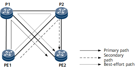
Hot standby supports best-effort paths. If both the primary and backup CR-LSPs fail, a temporary path, called a best-effort path, is established. All traffic switches to this path. In Figure 1, the path of the primary CR-LSP is PE1 -> P1 -> PE2, and the path of the backup CR-LSP is PE1 -> P2 -> PE2. If both the primary and backup CR-LSPs fail, the node triggers the setup of a best-effort path along the path PE1 -> P2 -> P1 -> PE2.
Pre-configuration Tasks
Before configuring CR-LSP backup, complete the following tasks:
Establish a primary RSVP-TE tunnel.
Enable MPLS, MPLS TE, and RSVP-TE in the MPLS and physical interface views on every node along a bypass tunnel. (See Enabling MPLS TE and RSVP-TE.)
(Optional) Configure the link bandwidth for the backup CR-LSP. (See (Optional) Configuring TE Attributes.)
(Optional) Configure an explicit path for the backup CR-LSP. (See (Optional) Configure an explicit path.)
- Configuring CR-LSP Backup Parameters
- A backup CR-LSP is established in either hot standby or ordinary backup mode. A hot-standby CR-LSP and an ordinary backup CR-LSP cannot be established simultaneously.
- (Optional) Configuring a Best-effort Path
- A best-effort path is configured to take over traffic if both the primary and backup CR-LSPs fail.
- (Optional) Configuring a Traffic Switching Policy for a Hot-Standby CR-LSP
- This section describes how to configure a traffic switching policy for a hot-standby CR-LSP. The traffic switching policy determines whether to switch traffic back to the primary CR-LSP and sets a switchback delay.
- (Optional) Configuring a Manual Switching Mechanism for a Primary/Hot-Standby CR-LSP
- This section describes how to configure a manual switching mechanism for a primary/hot-standby CR-LSP. This mechanism allows you to control primary/hot-standby CR-LSP switchovers using commands.
- (Optional) Configuring CSPF Fast Switching
- The CSPF fast switching function enables Hot-standby to switch quickly.
- (Optional) Enabling the Coexistence of Rapid FRR Switching and MPLS TE HSB
- When FRR and HSB are enabled for MPLS TE tunnels, enabling the coexistence of MPLS TE HSB and rapid FRR switching improves switching performance.
- Verifying the CR-LSP Backup Configuration
- After configuring CR-LSP backup, you can view information about backup CR-LSPs.