Multicast VPLS
Background
- IP multicast: An IP multicast network is complex to deploy and maintain. The network does not have QoS or TE capabilities and provides low reliability.
- Layer 2 multicast: A large Layer 2 multicast network must use the HVPLS technology and solve routing loop problems. The network is complex to deploy and its reliability scheme is hard to design.
To provide better multicast services, IETF proposed the multicast VPLS solution. On a multicast VPLS network, the ingress directly transmits multicast traffic to multiple egresses over a P2MP MPLS tunnel. This solution eliminates the need to deploy PIM and HVPLS on the transit nodes of tunnels, simplifying network deployment. In addition, multicast VPLS can utilize the advantages of MPLS in TE, QoS guarantee, and reliability assurance.
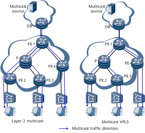
Multicast VPLS reduces redundant multicast traffic on the network by replicating multicast traffic on demand. Figure 1 shows the differences between Layer 2 multicast and multicast VPLS in multicast traffic replication. On the Layer 2 multicast network, the multicast traffic is replicated into three copies right at the ingress PE1. On the multicast VPLS network, the multicast traffic is replicated on demand at each node. Compared with Layer 2 multicast, multicast VPLS reduces the burden of links.
Related Concepts
Name |
Description |
Corresponding Device |
|---|---|---|
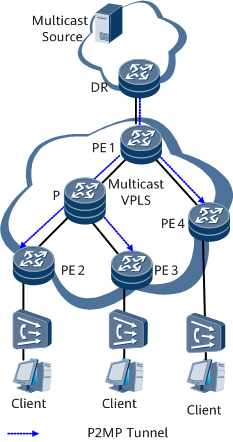
Root node |
Ingress of a P2MP tunnel. |
PE1 in Figure 2 |
Branch node |
A type of transit node. A branch node replicates each incoming packet and swaps the label in the incoming packet with another label before forwarding the packet to each leaf node. |
P in Figure 2 |
Leaf node |
Egress of a P2MP tunnel. |
PE2, PE3, and PE4 in Figure 2 |
Implementation
Tunnel establishment
Compared Aspect |
P2MP TE Tunnel |
P2MP mLDP Tunnel |
|---|---|---|
Usage scenario |
Networks that require control over destination nodes |
Networks that do not require control over destination nodes |
Creation mode |
The root node initiates LSP setup. |
The leaf nodes initiate LSP setup. |
Signaling |
The P2MP tunnel is maintained by periodically sent signaling packets. If a large number of leaf nodes exist, network congestion is likely to occur. |
Signaling packets do not need to be periodically sent, reducing network pressure. |
- Tunnel type being P2MP TE
- After the tunnel type is configured as P2MP TE for the root node VSI, the VSI applies for tunnel FEC information from root node TE.
- The root node VSI notifies root node TE of the IP addresses of all VSI peers (leaf nodes).
- Root node TE sends TE signaling packets to all leaf nodes to trigger P2MP tunnel establishment.
- Leaf node TE establishes the P2MP tunnel after receiving TE signaling packets from root node TE.
- Tunnel type being P2MP mLDP
- After the tunnel type is configured as P2MP mLDP for the root node VSI, the VSI applies for tunnel FEC information from root node mLDP.
- The root node VSI sends tunnel FEC information to all VSI peers (leaf nodes) using BGP AD or BGP Multi-homing signaling packets.
- Leaf node VSIs parse BGP AD or BGP Multi-homing signaling packets and notify leaf node mLDP of tunnel FEC information.
- Leaf node mLDP sends mLDP signaling packets to the root node to trigger P2MP tunnel establishment based on tunnel FEC information.
- Root node mLDP establishes the P2MP tunnel after receiving mLDP signaling packets from leaf node mLDP.
After the P2MP tunnel is established, PE1 sends the multicast traffic received from the DR to each leaf node over the P2MP tunnel. The leaf nodes replicate the multicast traffic on demand before sending the traffic to multicast receivers.
Data forwarding
Node |
Forwarding Entry |
Forwarding Behavior |
|
|---|---|---|---|
Incoming Label |
Outgoing Label |
||
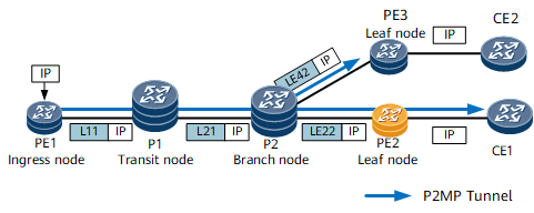
PE1 |
N/A |
L11 |
Pushes an outgoing label with the value of 11 into an IP multicast packet and forwards the packet to P1. |
P1 |
L11 |
L21 |
Swaps the incoming label with an outgoing label with the value of 21 in an MPLS packet and forwards the packet to P2. |
P2 (branch node) |
L21 |
LE22 |
Replicates the IP multicast packet, swaps the incoming label with an outgoing label in each packet, and forwards each packet to a next hop through a specific outbound interface. |
LE42 |
|||
PE2 |
LE22 |
None |
Removes the label from the packet so that this MPLS packet becomes an IP multicast packet. |
PE3 |
LE42 |
None |
Removes the label from the packet so that this MPLS packet becomes an IP multicast packet. |
Benefits
- Optimizes bandwidth usage.
- Provides bandwidth assurance for multicast services.
- Simplifies network deployment by eliminating the need to deploy multicast protocols, such as PIM, on the core nodes of the backbone network.