S2720-28TP-EI
Version Mapping
Table 1 lists the mapping between the S2720-28TP-EI chassis and software versions.
Appearance and Structure
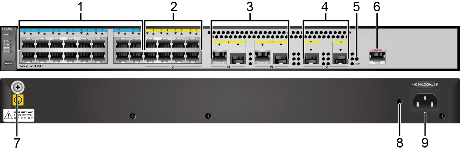
| 1 | Sixteen 10/100BASE-TX ports | 2 | Eight 10/100/1000BASE-T ports |
| 3 | Two combo ports (10/100/1000BASE-T + 100/1000BASE-X) Modules applicable to combo optical ports:
|
4 | Two 1000BASE-X ports Applicable modules and cables:
NOTE:
If a port uses a GPON optical module, other 1000BASE-X optical ports cannot be used. |
| 5 | PNP button NOTICE:
Applicable in V200R012C00 and later versions: To restore the factory settings and reset the switch, hold down the button for at least 6 seconds. To reset the switch, press the button. Resetting the switch will cause service interruption. Exercise caution when you press the PNP button. |
6 | One console port |
| 7 | Ground screw NOTE:
It is used with Ground cable. |
8 | Jack reserved for AC power cable locking strap NOTE:
The AC power cable locking strap is not delivered with the switch. |
| 9 | AC socket NOTE:
It is used with AC Power Cable. |
- | - |
Port Description
10/100BASE-TX port
By default, a combo port works in auto mode, in which the port type is determined as follows:
- If the optical port has no optical module installed and the electrical port has no Ethernet cable connected, the port type depends on which port is connected first. If the electrical port is connected by an Ethernet cable first, the electrical port is used for data switching. If the optical port has an optical module installed first, the optical port is used for data switching.
- If the electrical port has an Ethernet cable connected and is in Up state, the electrical port is still used for data switching when the optical port has an optical module installed.
- If the optical port, no matter in Up or Down state, has an optical module installed, the optical port is still used for data switching when the electrical port has an Ethernet cable connected.
- If the optical port has an optical module installed and the electrical port has an Ethernet cable connected, the optical port is used for data switching after the switch restarts.
Indicator Description
The S2720-28TP-EI has similar indicators to those on the S2720-28TP-PWR-EI, except that the S2720-28TP-EI does not have a PoE mode indicator. For details, see Indicator Description.Power Supply Configuration
The S2720-28TP-EI has a built-in power module and does not support pluggable power modules.
Heat Dissipation
The S2720-28TP-EI has no fans and uses natural heat dissipation.
Technical Specifications
Table 6 lists technical specifications of the S2720-28TP-EI.
Item |
Description |
|---|---|
Memory (RAM) |
512 MB |
Flash |
512 MB in total. To view the available flash memory size, run the display version command. |
Mean time between failures (MTBF) |
49 years |
| Mean time to repair (MTTR) | 2 hours |
Availability |
> 0.99999 |
Service port surge protection |
Common mode: ±7 kV |
Power supply surge protection |
±6 kV in differential mode, ± 6 kV in common mode |
Dimensions (H x W x D) |
43.6 mm x 442.0 mm x 220.0 mm (1.72 in. x 17.4 in. x 8.7 in.) |
Weight (including package) |
4 kg (8.82 lb) |
Stack ports |
Two 1000BASE-X ports |
RTC |
Not supported |
RPS |
Not supported |
PoE |
Not supported |
Rated voltage range |
100 V AC to 240 V AC, 50/60 Hz |
Maximum voltage range |
90 V AC to 264 V AC, 47 Hz to 63 Hz |
Maximum power consumption (100% throughput) |
20.1 W |
Typical power consumption (30% of traffic load)
|
15.2 W |
Operating temperature |
0°C to 45°C (32°F to 113°F) at an altitude of 0-1800 m (0-5906 ft.)
NOTE:
When the altitude is 1800-5000 m (5906-16404 ft.), the highest operating temperature reduces by 1°C (1.8°F) every time the altitude increases by 220 m (722 ft.). The operating temperature of the switch is 0°C to 40°C (32°F to 104°F) when it uses GE SFP optical modules with 40 km transmission distance. |
Short-term operating temperature |
-5°C to +50°C (23°F to 122°F) at an altitude of 0-1800 m (0-5906 ft.) NOTE:
When the altitude is 1800-5000 m (5906-16404 ft.), the highest operating temperature reduces by 1°C (1.8°F) every time the altitude increases by 220 m (722 ft.). The equipment can operate beyond the normal operating
temperature range for a short-term period, but the following conditions
must be met:
The equipment cannot start when the temperature is lower than 0°C (32°F). The maximum distance of optical modules used in these conditions cannot exceed 10 km. |
Storage temperature |
-40°C to +70°C (-40°F to +158°F) |
Noise under normal temperature (27°C, sound power) |
Noise-free (no fans) |
Relative humidity |
5% to 95%, noncondensing |
Operating altitude |
0-5000 m (0-16404 ft.) |
Certification |
|
| Part number | 98010680 |